Download
1 / 17
180 likes | 436 Views
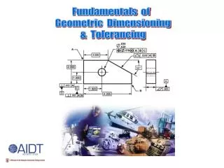
Dimensioning Fundamentals. Dimensioning Fundamentals. Key Concepts. Dimensions are used to define and describe size and locations. Dimension, extension, and leader lines are used on drawings to assist in the communication information .

E N D
Dimensioning Fundamentals Key Concepts • Dimensions are used to define and describe size and locations. • Dimension, extension, and leader lines are used on drawings to assist in the communication information. • Fractional and decimal are two types of inch dimensions.
Dimensioning Fundamentals Key Concepts • Metric dimensioning is also used on industrial drawings. • General and local notes are used on drawings to further clarity. • There aregeneral rulesfor good dimensioning that should always be followed.
General Rules • Take your time and provide adequate room • Dimension lines should be thin and contrast with lines from drawing • Dimension each feature in the view which most completely shows it’s characteristics
More General Rules • Extension lines may cross when necessary but avoid crossing dimension lines with extension lines or leaders. • Avoid duplications of dimensions • Make sure dimensions can only be interpreted one way.
Dimensioning Fundamentals Dimensioning Terminology • DimensionLine • Line with termination symbols, generally arrowheads, at each end to indicate the direction and extent of a dimension.
1/4” 3/8” Dimensioning Fundamentals Dimensioning Terminology • DimensionLine
Dimensioning Fundamentals Dimensioning Terminology • ExtensionLine • Lines used to indicate the termination of a dimension. They are usually drawn perpendicular to the dimension line.
1/8” 1/16” Visible Gap Dimensioning Fundamentals Dimensioning Terminology • ExtensionLine
Dimensioning Fundamentals Dimensioning Terminology • Leaders • Thin, straight lines that lead from a note or dimension to a feature on the drawing. They terminate with an arrowhead.
1/16” 45 to 60 Dimensioning Fundamentals Dimensioning Terminology • Leaders
.089 Drill 6 Holes Dimensioning Fundamentals Dimensioning Terminology • Dimensional Notes • Used to describe size or form, such as specifying holes, chamfers and threads.
1 3 2 Dimensioning Fundamentals Dimensioning Figures • Placement of Dimensioning Figures • Common fractions and decimals are centered in a break in the dimension line.
1 3 2 1 1 2 Dimensioning Fundamentals Dimensioning Figures • Unidirectional Systems • All dimensions figures are placed to be read from the bottom of the drawing.
1 3 2 1 1 2 Dimensioning Fundamentals Dimensioning Figures • Aligned Systems • All dimensions figures are placed parallel to their dimension lines.
Top Top Front Rt Front Rt Dimensioning Fundamentals Dimensioning Figures • Outline of Objects • All dimensions figures should be kept outside the views of an object whenever possible.
Top 2” Front Rt 2” Dimensioning Fundamentals Dimensioning Layout • Drawing Window • Spacing between views will be TWO inches.