Basic Dimensioning
Basic Dimensioning. Definitions. Dimensions are given on drawings by extension lines, dimension lines, leaders, arrowheads, figures, notes and symbols Length Diameter Angle Location NOT duplicated Dimension lines are used to determine the extent and direction of dimensions

Basic Dimensioning
E N D
Presentation Transcript
Definitions • Dimensions are given on drawings by extension lines, dimension lines, leaders, arrowheads, figures, notes and symbols • Length • Diameter • Angle • Location • NOT duplicated • Dimension lines are used to determine the extent and direction of dimensions • Terminated by uniform arrows • Arrows: 3:1 length/width recommended • Center lines never used for dimension lines • Avoid dimensioning to hidden lines • Avoid crossing dimension lines • Place dimension lines outside extension lines when space is tight
Definitions continued… • Extension lines are used to indicate the point or line on the drawing to which the dimension applies • Gap between extension line and visible object line • Perpendicular to dimension lines • Center lines may be used as extension lines • Leaders are used to direct notes, dimensions, symbols, item numbers, or part numbers to features on a drawing • Arrowheads terminate on a line; dots within the outline of the object • Leaders do not cross each other • Leaders are pointed to the center of circles or arcs • Notes are used to simplify or complement dimensioning by giving information on a drawing in condensed and systematic manner • General notes placed in a central portion below the view which they apply • Local notes are connected by a leader to the point to which they apply
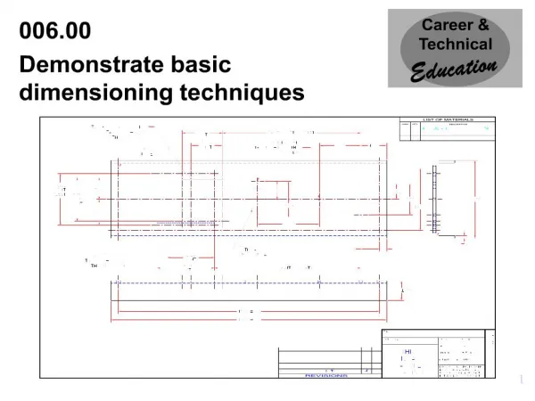
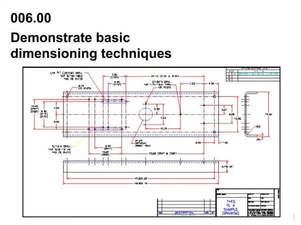
Overview: • Dimensions and notes define the size, finish, and other requirements to fully define what you want manufactured. • Drawings for products must be dimensioned so that production personnel all over the world can make mating parts that will fit properly when assembled or when used to replace parts.
Good Dimensioning • 3 Aspects of Good Dimensioning • Technique: • Good appearance of lines, spacing and arrows to allow others to read the drawing. • Placement: • Logical placement according to standard practices, so they are legible and east to find. • Choice: • Dimension for function and best manufacturing practices. • Tolerance • The total amount that the feature on the actual part can vary from the drawing or model.
INCORRECT PLACEMENT OF DIMENSIONS
INCORRECT PLACEMENT OF DIMENSIONS
INCORRECT PLACEMENT OF DIMENSIONS
PLACEMENT OF DIMENSIONS CORRECT
Units of measurement • Decimal-Inch parts are designed in basic decimal increments, preferably .02 in, and expressed with a minimum of two figures to the right of the decimal point • Whole dimensions: 24.00 NOT 24 • Decimal dimensions: .44 NOT 0.44 (no zero before the decimal point) • Fractional-Inch is not ANSI recommended. 1/64 inch. “ not used • Foot-and-Inch All dimensions 12 inches and greater are specified in feet and inches • 24 inches 2’-0 (inch marks “ not shown) • 27 inches 2’-3 • SI Metric Units mm or m (micrometer) • Whole numbers 2 NOT 02 or 2.0 (numbers 1-9 shown without zero to left of decimal) • Decimal 0.2 NOT .2 or .20 (numbers <1 shown with a zero) • Large numbers 32545 (no comma or spaces to separate digits) • General note like: unless otherwise specified dimensions are in millimeters
DIMENSIONING UNITS DECIMAL INCH
DIMENSIONING UNITS FEET AND INCHES
Worth mentioning • Dual Dimensioning specify both English/SI units but not generally used anymore • Angular Units decimal degree is preferred over degrees, minutes, seconds • 60.5° instead of 60°30’
DUAL DIMENSIONING and COMBINATION UNITS Dual dimensioning is used to show metric and decimal-inch dimensions on the same drawing. Two methods of displaying the dual dimensions are: Position Method Bracket Method DIMENSIONS IN () ARE MILLIMETERS
Unidirectional dimensioning: read from the bottom of the drawing • Rules for Basic Dimensioning • Symmetrical Outlines • Reference dimensions placed in parentheses • Not to scale underlined with a straight thick line
DIMENSION SYMBOLS Dimensioning symbols are used to replace traditional terms or abbreviations.
NECESSARY VIEWS What are the absolute minimum views required to completely define an object? One-View Drawing Two-View Drawing Three-View Drawing
BASIC RULES FOR DIMENSIONING UNIDIRECTIONAL USED ON ENGINEERING DRAWINGS
BASIC RULES FOR DIMENSIONING ALIGNED USED ON ARCHITECTURAL AND STRUCTURAL DRAWINGS
BASIC RULES FOR DIMENSIONING PLACE DIMENSIONS BETWEEN VIEWS
BASIC RULES FOR DIMENSIONING PLACE SMALLEST DIMENSIONS NEAREST THE VIEW BEING DIMENSIONED
Dimensioning Circular Features • Diameters • One view drawing-longitudinal view • End view drawing • Radii-circular arc • Passes through radius center and terminates with arrow touching arc • R precedes the numerical value • Cross at center of radius • Simple fillets and rounds dimensioned with a general note • Cylindrical Holes-leader usually used • Multiple Holes – example 4 X ф8.4
Countersink, Counterbore, Spotface • Countersink is an angular-sided recess that accommodates the head of flathead screws, rivets, and similar items [ф.40ф.80x82°] • Counterbore is a flat-bottomed, cylindrical recess that permits the head of a fastening device, such as a bolt, to lie recessed into the part[ф.38v ф .75x.25] • Spotface is an area in which the surface is machined just enough to provide smooth, level seating for a bolt head, nut, or washer [ф.38 v ф.75]
Dimensioning common features • Repetitive features and dimensions use an X in conjunction with the numeral to indicate the “number of times” • Chamfering is the process of cutting away the inside or outside piece • Dimensioned normally by their angle and linear length • Example: 45°X.10 • Slopes and tapers • Slope is the slant of a line • A taper is the ratio of the difference in the diameters of two sections • Knurls is specified in terms of type, pitch, diameter before and after knurling Types include: Straight, Diagonal, Spiral, Convex, Raised Diamond • Undercutting or necking is the operation of cutting a recess in a diameter that is done to permit two parts to come together