
Update on PSI/Trieste X-Band Phase Space Rotator Structure Engineering
This paper presents the engineering design updates for the multi-purpose X-band RF accelerating structure developed by PSI, Elettra, and CERN. It focuses on the construction of a system consisting of disked cells joined by diffusion bonding, along with vacuum brazing and laser beam welding for auxiliary components. Key features include coupler subassemblies, a wakefield monitor, and integrated cooling and RF tuning systems. Detailed discussions on the fabrication precision, thermal management, and sealing techniques for monitoring devices are included, showcasing advancements in accelerator technology.

Update on PSI/Trieste X-Band Phase Space Rotator Structure Engineering
E N D
Presentation Transcript
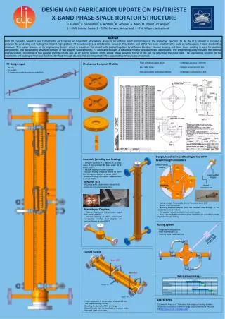
DESIGN AND FABRICATION UPDATE ON PSI/TRIESTE X-BAND PHASE-SPACE ROTATOR STRUCTURE 2 1 2 1 2 3 3 D. Gudkov, A. Samoshkin, G. Riddone, R. Zennaro, S. Atieh, M. Dehler, J-Y. Raguin 1 – JINR, Dubna, Russia; 2 - CERN, Geneva, Switzerland; 3 - PSI, Villigen, Switzerland Abstract Both FEL projects, SwissFEL and Fermi-Elettra each require an X-band RF accelerating structure for optimal bunch compression at the respective injectors [1]. As the CLIC project is pursuing a program for producing and testing the X-band high-gradient RF structures [2], a collaboration between PSI, Elettra and CERN has been established to build a multipurpose X-band accelerating structure. This paper focuses on its engineering design, which is based on the disked cells jointed together by diffusion bonding. Vacuum brazing and laser beam welding is used for auxiliary components. The accelerating structure consists of two coupler subassemblies, 73 disks and includes a wakefield monitor and diagnostic waveguides. The engineering study includes the external cooling system, consisting of two parallel cooling circuits and an RF tuning system, which allows phase advance tuning of the cell by deforming the outer wall. The engineering solution for the installation and sealing of the wake field monitor feed-through devices that are integrated in the accelerating structure are presented. • Thick cylindrical copper disks; • Four radial holes; • Slots and cavities for brazing material • Cell shape accuracy 0.004 mm • Flatness accuracy 0.002 mm • Cell shape roughness Ra 0.025 RF-design input Mechanical Design of RF disks • 73 cells • 2 couplers • 2 special regions for monitoring wakefields Water OUT Design, Installation and Sealing of the WFM Feed-through Connectors Assembly (bonding and brazing) Water OUT • Diffusion bonding of 3 stacks (24..25 disks each) of high-precision RF disks under H2 at about 1035°C • - Vacuum brazing of stacks together • - Vacuum brazing of special inserts for WFM feed-through connectors at about 800°C • Vacuum brazing of couplers subassemblies at about 760°C Electron-beam welding Water IN Laser welded Adapter Water IN BONDING TEST Metallographic observation shows that grains are crossing joining plane Special connector end • Custom design. Produced by Orient Microwave Corp. [2] • Special end of connector • - Specially designed adapter from the standard feed-through to the accelerating structure body • The adapter is laser welded to the feed-through • Final, vacuum tight connection of the feed-through assembly is made by electron beam welding Tuning System Assembly of Couplers • Vacuum brazing of high-precision copper disks at about 800°C • - Vacuum brazing of other components: waveguides, stainless steel adapters and vacuum flanges at about 760°C Push-Pull • Integrated tuning system; • Push-Pull Principle [1]; • 4 tuning studs inside each cell. Cooling System Fabrication strategy REFERENCES [1] Juwen W. Wang et al. “Fabrication Technologies of the High Gradient Accelerator Structures at 100MV/m Range”, paper presented at IPAC2010. [2] http://www.orient-microwave.com/ • Power dissipation in the structure of about 0.3 kW; • Two parallel cooling circuits; • 8 cooling blocks each of 394 mm long; • Brazed directly onto the accelerating structure body; • Standard water connectors.


