Download
1 / 19
190 likes | 307 Views
This research focuses on the design and development of a direct conversion multiband/multimode transmitter aimed at enhancing wireless communication. By utilizing fewer components, the transmitter can achieve cost efficiency while allowing access to multiple frequency bands. The project encompasses various stages, including circuit design, fabrication, and experimental results showcasing performance metrics like spectral plots and SWR analysis. Future work will address challenges such as the power amplifier's state-of-the-art requirements and switching inefficiencies.

E N D
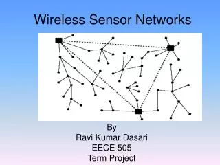
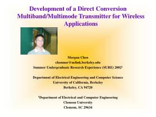
Development of a Direct Conversion Multiband/Multimode Transmitter for Wireless Applications Morgan Chen chenmor@uclink.berkeley.edu Summer Undergraduate Research Experience (SURE) 20021 Department of Electrical Engineering and Computer Science University of California, Berkeley Berkeley, CA 94720 1Department of Electrical and Computer Engineering Clemson University Clemson, SC 29634
Outline • Motivation/Objectives • Development and Design • Fabrication of Transmitter • Experimental Results • Conclusion
Motivation/Objectives • Direct Conversion, or homodyne, has fewer components • Fewer Components = Cheaper • Multiband transmitters allow accessing multiple frequencies • Ultimate goal of single chip design
Development and Design • Block Diagram • CircuitCAM
Design in CircuitCAM Example layout of switch Example layout of 5.8 GHz patch antenna
Experimental Results Spectral plot of the SKY-7G mixer with IF = 100 KHz, LO = 1.9 GHz
Just Curious Transmitter with mixer and antenna alone at 5 feet
Conclusions • Direct conversion multiband/multimode transmitter technology is promising • Design may require state of the art power amplifiers • Switch is inefficient • Switch also suffers from parasitics • Future research means developing the PA and switch • Future research also requires spectral masking
Acknowledgements • National Science Foundation • Minicircuits’s Gerry Edson • Agilent Technologies’ Creg Ballou • NEC's California Eastern Laboratories' David Melton and Pam Cowan • SURE advisor Dr. A. Pham • Graduate students S. Thumaty, D. Newlin, C. Tompkins, X. Wang, S. Manohar, J. Rudbeck, M. Lockhard, R. Hanks, S. Chopra, and A. Keerti • And last, but not least, Dr. D. Noneaker, Director of the SURE program at Clemson University
Additional Slides • Power Budget • Transistor diagram of the switching network • ADS • Baseband Harmonic Problem
Design in Advanced Design System Transmitter Block Diagram ADS Linecalc Tool
Baseband Harmonic Images Problem Small baseband frequencies = Spurious signals close to transmit signal!