Download

1 / 108
1.1k likes | 1.54k Views
Lesson Three Text Diesel engine construction (II). 1.Pistons and Piston rods. A piston consists of a lower part— piston skirt( 活塞裙 ) of cast iron and an upper part or crown( 活塞头 ) made of a special heat-resistant steel . They are bolted together and fixed to the piston rod. Piston crown.

E N D
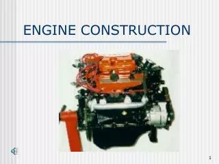
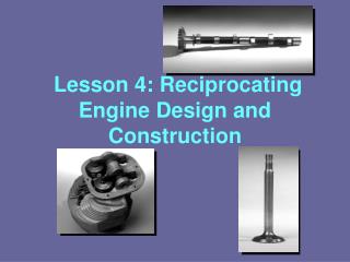
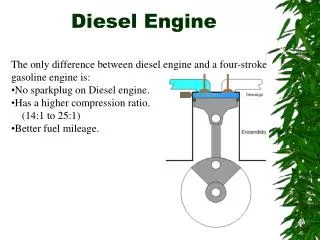
Lesson Three Text Diesel engine construction (II)
1.Pistons and Piston rods A piston consists of a lower part—piston skirt(活塞裙) of cast iron and an upper part or crown(活塞头)made of a special heat-resistant steel. They are bolted together and fixed to the piston rod.
Piston crown Piston ring Piston rod Piston skirt
The position of the piston parts in relation to each other is secured by means of machine-turned recesses(凹槽) and a dowel pin(定位销) in the crown.
Each piston is provided with five or six piston rings fitted in chromium plated grooves in the crown. The two or three topmost rings are narrow rings having diagonal cuts(斜切口式), while the next two are broad and are provided with overlapping end joints.
Overlapping end joint Diagonal cuts The lowest ring is an oil distributor ring.
External top External bottom All the rings are slightly rounded on theirexternal top and bottomedges to keep the oil film on the cylinder liner during the running-in period(跑合期、磨合期) for new piston rings.
In order to control thermal stresses, thin-wall intensively cooled pistons(薄壁强制冷却式活塞) are used for some types of modern engines.
In this case, the piston has an internal insert in the piston crown, which serves only to direct the cooling liquid flow and, thereby, to intensify the conventional ‘cocktail shaker(振荡冷却)' effect.
The piston rods are bored from the top flange to a point oppositethe center of the crosshead(十字头). Through this bore, a long pipe is inserted which goes nearly to the bottom of the bore.
Annular space The outside diameter of the pipe is less than the diameter of the bore, the result being that an annular space is formed between the piston rod and the pipe.
The lower end of each piston rod is reduced in diameter to fit a bore in the crosshead, this being secured to the piston rod by a nut. The piston rods are provided with dowel pins to ensure the correct assembly of the components.
Piston rod Crosshead
On each of the twojournals of the crosshead, crosshead shoes(十字头滑板) are mounted which are guided in the built-in crosshead guides(十字头导板) of the engine frame.
Crosshead shoe Engine frame Crosshead Crosshead guide
The position of the crossheadshoes on the crosshead is determined by dowelpins. The guide shoes are secured to the crosshead by means of tap-bolts(锥体螺钉).
The crosshead shoes are white metal lined(白合金衬里), grooves being cut horizontally in the face of the white metal to ensure an adequate supply of lubricating oil.
The crosshead is short and rigid and the bearings are so constructed that the bearing pressure between the journal and bearing is distributed evenly over the entire length of the bearing.
In order to improve the working conditions of the bearings, the bearing pressure is made smaller and the peripheral speed (is made) higher in later designs.
The pistons are cooled by oil supplied from the forced lubrication system.
The cooling oil is admitted through the pipe, from which the oil is led to the cooling spaces of the piston through telescopic pipes(伸缩管) or articulated pipe(铰接管), and round the internal pipes of the piston rods.
The cooling oil is conducted from the piston through the internal pipes of the piston rods and the ducts in the crossheads, as well as the slotted pipes from which the oil is led to “control boxes” with sight glasses(观察镜) on the engine.
Sealing between the crankcase and scavenging air boxes is achieved by means of the piston rod stuffing boxes, located in the bottom of the scavenging air boxes. Each stuffing is provided with two sealing rings and three scraper rings.
The sealing rings, which are mounted uppermost are in four parts and pressed together around the piston rods by means of coil springs(盘簧).
Connecting Rod and Main Bearings The crosshead and crankpin bearings (曲柄销轴承) are made of cast steel and each consist of an upper and a lower part secured to the connecting rod by means of fitted bolts(拂配螺栓), the nut of which are secured.
The bearings have white metal bearing surfaces provided with lubrication grooves for the necessary supply of lubricating and cooling oil.
Shims(垫片,调整片) of different thickness are inserted between the shells to enable adjustment of the bearing clearances (approx. 0.20-0.30mm).
The main bearings, which support the crankshaft, each consist of two shells of cast steel with white metal bearing surfaces having lubricating grooves of an appropriate shape.
The shells are secured by means of bearing caps and studs, the necessary clearance (approx. 0.30mm) being provided by means of shims of different thickness.
All bearings are lubricated from the force-feed lubrication system of the engine, the oil being supplied partly through pipes to each main bearing cap and partly to the crosshead, from where the lubricating oil flows through channels to the crankpin bearings.
3. Crankshaft 曲柄销 Crankpin 曲柄臂 Crank throw(web) Main bearing journal 主轴颈 Flywheel 飞轮
The crankshafts are built up types(组合式). For semi-built type(半组合式), the forged main bearing journals are shrunk(红套)into cast steel crank throws with a crank journal and two crank throws as one unit.
In the fully built type(全组合式), the crank throws are shrunk on to main journals and crank journals. The crank throws are displaced from each other to obtain the same number of degrees between the different crank throws.
The crankpin journals are provided with large bores for balancing purpose.
Reading Material M.A.N. Marine diesel engine
The latest large bore two stroke M.A.N. engine is the KSZ 90/160B series in cylinder numbers from 6 to 12 and developing 2,700 K.W. (3,672H.P.)/cyl.
The engine operates at 122 rev/min. with an M.E.P.(mean effective pressure平均有效压力) of 13 bar and a mean piston speed of 6.5m/sec.
The bedplate is of fabricated design and consists of two I-shaped longitudinal girders with transverse members into which the cast steel bearing housings are welded.
Columns(机架) have been replaced by framesconstructed of box shaped longitudinal girders. The fabricated top and bottom sections run the full length of the engine and are mounted on the bedplate.
Such an engine frame helps to stiffen the engine and so protect the bearings from the deformation forcestransmitted(传递) via the ship’s double bottom.
The cast iron guideways(导板) for the crosshead are attached to the top section and seal off the crankcase.
The cylinder jackets are individual castings(铸件) bolted together to form one continuous member.
The one-piece cylinder liners are fitted into the jackets from the top and a cast steel strong back is fitted in way of the combustion space to help absorb gas forces.
*The scavenge process is the M.A.N.loop system(回流扫气系统) and the scavenge and exhaust ports are arranged in two tiers and are carried far aroundthe liner.
The vertical lands between the ports are cooled by water passing through cast in tubes and thence to passages arranged around the liner above the exhaust ports.
Each cylinder cover is in two parts, the lower section is of special thin walled forged steel permitting the area in way of the combustion gases to be intensively cooled whilst absorbing thermal stresses
and this is held in position by an upper supporting unit of cast iron, which transmits the gas forces to the cylinder jackets via long studs.
The joint face between the cylinder cover and the liner is arranged as far away from the combustion process as possible.