Download
1 / 27
280 likes | 528 Views
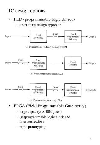
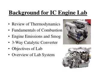
IC Engine Design Strategies Vs Exhaust Emissions. P M V Subbarao Professor Mechanical Engineering Department. An Efficient Engine Design is not Obviously Eco-friendly Design… Concentration of any chemical is pollution but not the quantity…. Emission sources in a gasoline fuelled car.

E N D
IC Engine Design Strategies Vs Exhaust Emissions P M V Subbarao Professor Mechanical Engineering Department An Efficient Engine Design is not Obviously Eco-friendly Design… Concentration of any chemical is pollution but not the quantity…..
Adverse Health Effects of IC Engine Generated Air Pollutants
Emissions Control • Three basic methods used to control engine emissions: • 1)Engineering of combustion process -advances in fuel injectors, oxygen sensors, and on-board computers. • 2) Optimizing the choice of operating parameters -two Nox control measures that have been used in automobile engines are spark retard and EGR. • 3) After treatment devices in the exhaust system -catalytic converter.
Three chemical reactions form the Zeldovich reaction are: Forward rate constants: Zelodvich reaction is the most significant mechanism of NO formation in IC engines.
Global Reaction Rate • Using the chemical reactions given, one can write the following expression for the rate of change of nitric oxide concentration. • Where the brackets denote concentrations in units of molecules/m3. • Approximations to solve above equation: • The C-O-H system is in equilibrium and is not perturbed by N2 dissociation. • This means that the pressure, temperature, equivalence ratio and residual fraction of fluid element only are required to calculate NO concentration. • N atoms change concentration by a quasi-steady process. • This means that one can solve for the N atom concentration by setting the rate of change of atoms to zero.
Using two approximations together: Where xNO is mass fraction of NO and a is the ratio of instantaneous NO mass fraction to equilibrium mass fraction of NO.
Practical Aspects of NOx Reactions • NO formation is kinetically controlled. • The NOx reactions are quasi steady. • The concentrations of [O2], [O], [OH], [H] & [N2] are in equilibrium. • Formation of N is slow and hence [N] is always in steady state. • The practical kinetics of formation of NO shows:
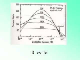
Effect of Various Parameters on NO Concentration Increased spark advance and intake manifold pressure both result in higher cylinder temperatures and thus higher NO concentrations in the exhaust gas
Exhaust NO Concentration Reduction • Since the formation of NO is highly dependent on cylinder gas temperature • any measures taken to reduce the AFT are effective: • increased residual gas fraction • exhaust gas recirculation (EGR) • moisture in the inlet air • In CI engines the cylinder gas temperature is governed by the load and injection timing
EGR System The EGR flow is directed by a solenoid valve that is controlled by the Power train Control Module (PCM). The PCM uses inputs such as engine speed, intake-manifold pressure, and engine temperature to determine how much exhaust flow to meter back to the air-fuel mixture.
Closing Remarks on NO Control • Unfortunately, EGR also reduces flame speed. • Excessive EGR rates can slow burn rate so drastically as to cause surge, misfire, and other combustion problems. • However, EGR can increase fuel economy. • When used optimally, EGR can reduce NO and improve fuel economy while avoiding rough engine operation. • This optimum varies with speed, load, and engine design. • Nox also varies with spark timing. • More spark advance means that parts of the mixture spend more time at high temperatures, so more NO is formed.
Hydrocarbon Emission Sources Crevices – these are narrow regions in the combustion chamber into which the flame cannot propagate because it is smaller than the quenching distance. Crevices are located around the piston, head gasket, spark plug and valve seats and represent about 1 to 2% of the clearance volume. The crevice around the piston is by far the largest, during compression the fuel air mixture is forced into the crevice and released during expansion.
Hydrocarbon Emission Sources for SI Engines There are six primary mechanisms believed to be responsible for hydrocarbon emissions: % fuel escaping Source normal combustion % HC emissions Crevices 5.2 38 Oil layers 1.0 16 Deposits 1.0 16 Liquid fuel 1.2 20 Flame quench 0.5 5 Exhaust valve leakage 0.1 5 Total 9.0 100
HC emission control: • Three basic types of emission control systems are used in modern vehicles; pre-combustion, post-combustion and evaporating control system. • Pre-combustion control; (Positive Crankcase Ventilation (PCV). • Engine Modification System; (Secondary air or air injector systems, and Catalytic converters). • The evaporative control system; (traps the fuel vapors from fuel tank, maniolds and carburetor).
Bore to Stroke Ratio Vs HC Emissions • There will be a direct consequence of lower heat losses at high S/B ratio and much greater than combustion higher combustion temperatures,. • These are associated with increasing the stroke and making the chamber portions more lean. • It could be speculated that the long-stroke (small-bore) engine would be advantageous in terms of unburned hydrocarbon emissions since crevice volumes, and hence trapped unburned charge in such volumes, much smaller in the small-bore engine.