Engine Emissions: Sources and Control Strategies
Explore the sources and impact of engine emissions in gasoline and diesel vehicles. Analyze pollutants like CO, HC, NOx, and PM, along with strategies to control emissions through combustion optimization and after-treatment devices.

Engine Emissions: Sources and Control Strategies
E N D
Presentation Transcript
IC Engine Emissions P M V Subbarao Professor Mechanical Engineering Department A Sad Story of Artificial Animal in Natural Environment…..
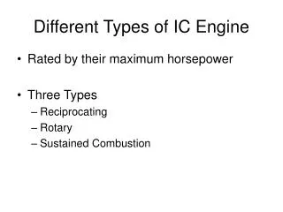
Engine Emissions Vs Combustion Strategy • Principal Engine Emissions • SI Engines : CO, HC and NOx • CI Engines : CO, HC, NOx and PM
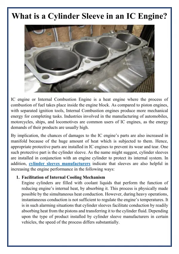
The Cylinder & Hydrocarbon Emission Sources All these collection centers accumulate air fuel mixture during compression. They release unburnt HCs during Expansion into Cylinder.
Hydrocarbon Release into Atmosphere Exhaust Process The first peak is due to blow down and the second peak is due to vortex roll up and exhaust (vortex reaches exhaust valve at roughly 290o) Exhaust valve closes Exhaust valve opens TC BC
Hydrocarbon Emission Sources for SI Engines There are six primary Sources believed to be responsible for hydrocarbon emissions: % fuel escaping Source normal combustion % HC emissions Crevices 5.2 38 Oil layers 1.0 16 Deposits 1.0 16 Liquid fuel 1.2 20 Flame quench 0.5 5 Exhaust valve leakage 0.1 5 Total 9.0 100
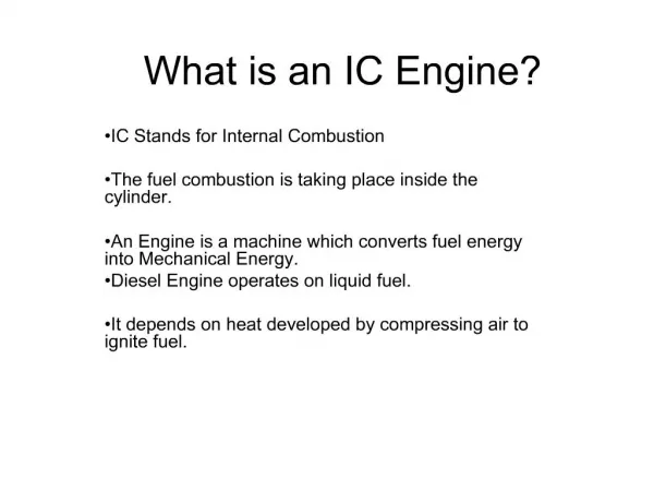
Formation of CO in IC Engines • Formation of CO is well established. • Locally, there may not be enough O2 available for complete oxidation and some of the carbon in the fuel ends up as CO. • The amount of CO, for a range of fuel composition and C/H ratios, is a function of the relative air-fuel ratio. • Even at sufficient oxygen level, high peak temperatures can cause dissociation. • Conversion of CO to CO2 is governed by reaction • Dissociated CO may freeze during the expansion stroke. The highest CO emission occurs during engine start up (warm up) when the engine is run fuel rich to compensate for poor fuel evaporation.
Air/Fuel Ratio Vs Carbon Monoxide Concentration : SI Engines
Particulates • A high concentration of particulate matter (PM) is manifested as visible smoke in the exhaust gases. • Particulates are any substance other than water that can be collected by filtering the exhaust, classified as: • Solid carbon material or soot. • Condensed hydrocarbons and their partial oxidation products. • Diesel particulates consist of solid carbon (soot) at exhaust gas temperatures below 500oC, HC compounds become absorbed on the surface. • In a properly adjusted SI engines soot is not usually a problem . • Particulate can arise if leaded fuel or overly rich fuel-air mixture are used. • Burning crankcase oil will also produce smoke especially during engine warm up where the HC condense in the exhaust gas.
Mechanism of Formation of Particulates (soot) The soot formation process is very fast. 10 – 22 C atoms are converted into 106 C atoms in less than 1 ms. Based on equilibrium the composition of the fuel-oxidizer mixture soot , formation occurs when x ≥ 2a (or x/2a ≥ 1) in the following reaction: Experimentally it is found that the critica C/O ratio for onset of soot formation is between 0.5 and 0.8. The CO, H2, and C(s) are subsequently oxidized in the diffusion flame to CO2 and H2O via the following second stage. Any carbon not oxidized in the cylinder ends up as soot in the exhaust!
NOx Formation in I.C. Engines Three chemical reactions form the Zeldovich reaction are: Forward rate constants: Zelodvich reaction is the most significant mechanism of NO formation in IC engines.
Global Reaction Rate • Using the chemical reactions given, one can write the following expression for the rate of change of nitric oxide concentration. • Where the brackets denote concentrations in units of molecules/m3. • Approximations to solve above equation: • The C-O-H system is in equilibrium and is not perturbed by N2 dissociation. • This means that the pressure, temperature, equivalence ratio and residual fraction of fluid element only are required to calculate NO concentration. • N atoms change concentration by a quasi-steady process. • This means that one can solve for the N atom concentration by setting the rate of change of atoms to zero.
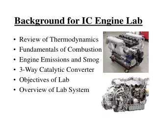
Emissions Control • Three basic methods used to control engine emissions: • 1)Engineering of combustion process -advances in fuel injectors, oxygen sensors, and on-board computers. • 2) Optimizing the choice of operating parameters -two Nox control measures that have been used in automobile engines are spark retard and EGR. • 3) After treatment devices in the exhaust system -catalytic converter.
Anatomy of Catalytic Converter for SI Engines • All catalytic converters are built in a honeycomb or pellet geometry to expose the exhaust gases to a large surface made of one or more noble metals: platinum, palladium and rhodium. • Rhodium used to remove NO and platinum used to remove HC and CO. Lead and sulfur in the exhaust gas severely inhibit the operation of a catalytic converter (poison).
Three-way Catalytic Converter • A catalyst forces a reaction at a temperature lower than normally occurs. • As the exhaust gases flow through the catalyst, the NO reacts with the CO, HC and H2 via a reduction reaction on the catalyst surface. • NO+CO→½N2+CO2 , NO+H2 → ½N2+H2O, and others • The remaining CO and HC are removed through an oxidation reaction forming CO2 and H2O products (air added to exhaust after exhaust valve). • A three-way catalysts will function correctly only if the exhaust gas composition corresponds to nearly (±1%) stoichiometric combustion. • If the exhaust is too lean – NO is not destroyed • If the exhaust is too rich – CO and HC are not destroyed • A closed-loop control system with an oxygen sensor in the exhaust is used to A/F ratio and used to adjust the fuel injector so that the A/F ratio is near stoichiometric.