Download

1 / 45
450 likes | 614 Views
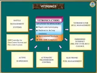
Matching Conducted EMI to International Standards. Presenter: Fernando Soares dos Reis Pontifical Catholic University of the Rio Grande do Sul Brazil. Table of Contents. INTRODUCTION OBJECTIVES TERMS AND DEFINITIONS - EMC, EMI PFCs CONDUCTED EMI SIMULATION FILTER DESIGN

E N D
Matching Conducted EMI to International Standards Presenter: Fernando Soares dos Reis Pontifical Catholic University of the Rio Grande do Sul Brazil 33 rd Power Electronics Specialists Conference
Table of Contents • INTRODUCTION • OBJECTIVES • TERMS AND DEFINITIONS - EMC, EMI • PFCs • CONDUCTED EMI • SIMULATION • FILTER DESIGN • CONCLUSIONS 33 rd Power Electronics Specialists Conference
INTRODUCTION Some examples of problems caused by EMI: • Pistol Drill may Interfere on TV; • Electronic Ballast's may change the TV channel; • Switching Inductive Load may generate noise in Radios; Necessity of accordance with Standards... 33 rd Power Electronics Specialists Conference
OBJECTIVES To easily determine the EMI levels on basic PFC and to design the EMI input filter in the design step facing the following points: • Main Standards • Simulation of the Conducted EMI • EMI Minimization Techniques 33 rd Power Electronics Specialists Conference
TERMS AND DEFINITIONS Electromagnetic Compatibility - EMC: • It´s the characteristic presented by an equipment, or system, working satisfactorily, in an electromagnetic environment without causing or suffering unacceptable degradation in its individually designed function. 33 rd Power Electronics Specialists Conference
INDUSTRIAL ENVIRONMENT EMI EMC 33 rd Power Electronics Specialists Conference
TERMS AND DEFINITIONS Electromagnetic Interference – EMI • Any electromagnetic disturbance that interrupts, obstructs, or otherwise degrades or limits the effective performance of electronics/electrical equipment. It can be induced intentionally, as in some forms of electronic warfare, or unintentionally, as a result of spurious emissions and responses, intermodulation products, and the like. Also called radio frequency interference RFI. 33 rd Power Electronics Specialists Conference
COMMUNICATIONENVIRONMENT EMC EMI 33 rd Power Electronics Specialists Conference
ALCA MERCOSUL EUROPEAN UNION By Globalization´s Highway...International Rules... 33 rd Power Electronics Specialists Conference
GLOBALIZATIONS • IEC - International Electrotechnical Commission; • CISPR - International Special Committee on Radio Interference; • CENELEC - Committee for Electrotechnical Standardization; • These organizations prepares and publishes international standards for all electrical, electronic and related technologies; 33 rd Power Electronics Specialists Conference
ELECTRONICS LOADS CONSUMERS REQUIREMENTS • IN THE LAST YEARS THE ELECTRONIC LOADS GROW UP OVER THE WORLD • BRAZIL WAS NOT AN EXEPTION AT THIS PROCESS EMC ELECTRONICS LOADS 33 rd Power Electronics Specialists Conference
C DC DC - DC CONVENTIONAL INPUT RECTIFIER LOW POWER FACTOR INPUT POWER LINE CAPACITORS VOLTAGE CC DIODES INPUT CURRENT POWER LINE CURRENT HIGH THD ELECTRONICS LOADS 33 rd Power Electronics Specialists Conference
PFPs To solve those problems it was created the PFPs • Power Factor Pre-Regulators • Power Factor Correctors • Input Pre-Regulators • Power Factor Rectifiers • Resistance Emulators ELECTRONICS LOADS 33 rd Power Electronics Specialists Conference
EMI Power Factor Pre-Regulators High Frequency Switching Noise Degrades the Power Quality. Input Voltage Input Current REMEMBER, PFP ARE GRID CONNECTED 33 rd Power Electronics Specialists Conference
100 100 90 90 Limit Value Limit Value 79 80 80 class A Quasi-peak (class A) dB 73 70 70 µV 70 66 dB 56 60 60 Limit Value 60 60 µV class B 50 48 50 Quasi-peak (class B) 40 40 30 30 0.01 0.1 0.45 1 1.6 MHz 30 10 5 30 MHz 0.15 0.5 10 0.9 LIMIT STANDARDS CISPR 11 FCC 15 Class A. A device that is marketed for use in a commercial, industrial or business environment; Class B A device that is marketed for use in a residential environment notwithstanding use in commercial, business and industrial environments; 33 rd Power Electronics Specialists Conference
CONDUCTED EMI It is the part of the electromagnetic interference that flows by power cords. This kind of interference can be propagated in: • Differential Mode (DM) or in • Common Mode (CM) 33 rd Power Electronics Specialists Conference
CONDUCTED EMI in DIFERENTIAL MODE Phase Z i LISN CDM Equipment Neutral 33 rd Power Electronics Specialists Conference
CONDUCTED EMI IN COMMON MODE Phase Z i LISN CCM Equipment Neutral Ground - Common Parasitic Capacitors 33 rd Power Electronics Specialists Conference
LABORATORY TESTS Equipment Under Test (EUT) and Measurements Apparatus Conductive Surface Connected to Gnd EMI Receiver Equipment Under Test 40 cm LISN 80 CISPR 16 80 cm cm Layout for conducted emissions tests 33 rd Power Electronics Specialists Conference
Conducted EMI test Difficulties for realization of the tests • Few test Facilities (in Brazil and South America); • Test apparatus are very expensive; • Technical Capacity; • Standards Interpretation; 33 rd Power Electronics Specialists Conference
AFTER LAB TESTS If your equipment did not attend the standard limits...What can you do? 33 rd Power Electronics Specialists Conference
LOW COST HOW TO MINIMIZE THE EMI? Preventives Actions: • Using Specific Control Methods; • Choosing the Best Topology; • Using Assembling Techniques; 33 rd Power Electronics Specialists Conference
In FM the Power Interference is Dispersed CONTROL ACTION HOW TO MINIMIZE THE EMI? For example, you can use a Variable Switching Frequency to Reduce de EMI INPUT CURRENT FM 10 1000 kHz SWITCHING FREQUENCY (Hz) 33 rd Power Electronics Specialists Conference
10 1000 kHz SWITCHING FREQUENCY (Hz) HOW TO MINIMIZE THE EMI? PWM Input Current Harmonic Spectrum INPUT CURRENT PWM In PWM the Power Interference is Concentrated 33 rd Power Electronics Specialists Conference
i i g d + + L D i ( t) + g ( t) i v C g g V AVG dc v R e - t - - HOW TO MINIMIZE THE EMI? Choosing a Topology with an inductor in series with the bridge rectifier. Because the EMI is a function of the input current ripple. 33 rd Power Electronics Specialists Conference
More expensive HOW TO MINIMIZE THE EMI? Correctives Actions: • Using Filter; • Applying Shielding; 33 rd Power Electronics Specialists Conference
Making the Conducted EMI Generated by Power Factor Pre-Regulators Compatible with the International Standards at the Design Time 33 rd Power Electronics Specialists Conference
Quantify EMI By Simulation SIMULATION Of the conducted EMI measurements apparatus according to CISPR 16 as proposed by ALBACH EMI Receiver 40 cm 80 80 cm cm FIRST OF ALL • Input Current • LISN • EMI Receiver 33 rd Power Electronics Specialists Conference
± 20 % Maximum Tolerance Fre. Imp. LISN kHz 10 5,4 Impedance () 50µH 20 7,3 80 21 50 5 150 33 300 43 800 49 10000 50 Frequency (MHz) SIMULATION OF THE LISN CHARACTERISTICS CISPR 16 LISN EMI Receptor 40 cm 80 80 cm cm 33 rd Power Electronics Specialists Conference
LISN Filter + I (t) g L int U (t) int R 2 R 1 - Demodulator Quase-Peak Detector + + + + R D R D 1D 1w C U (t) U (t) U (t) U (t) D int CD R C D w R 2D 2w w - - - - SIMULATION OF THE COMPLETE MEASURING SYSTEM Model for the measuring system 33 rd Power Electronics Specialists Conference
dB µV SWITCHING FREQUENCY (MHz) EMI SIMULATION RESULT EMI SIMULATION EXAMPLE 33 rd Power Electronics Specialists Conference
dB M = 1,23 µV M = 1,62 M = 2,01 M = 2,39 M = 2,78 M = 3,16 SWITCHING FREQUENCY (MHz) GENERATED ABACUS Using the proposed abacus we can determine the amplitude of the EMI (first harmonic) in dB/mV in accordance with the CISPR 16 standard, without simulation, for the following converters: • Boost • Buck-Boost • Zeta • Sepic • Cuk • Buck Abacus 33 rd Power Electronics Specialists Conference
GENERATED ABACUS • The EMI design curves (ABACUS) were built for an specific case (Reference Converter). • How to correlate the results from the abacus with a real case? 33 rd Power Electronics Specialists Conference
GAIN EQUATIONS U (dB/V) = 20 log P V + U (dB/V) USING THE GAIN EQUATIONS! ref g ref nom nom P V g nom ref Abacus 33 rd Power Electronics Specialists Conference
dB M = 1,23 µV M = 1,62 M = 2,01 M = 2,39 M = 2,78 M = 3,16 GAIN EQUATIONS U (dB/V) = 20 log P V + U (dB/V) g ref ref nom nom P V g nom ref Abacus SWITCHING FREQUENCY (MHz) 33 rd Power Electronics Specialists Conference
EXPERIMENTAL RESULTS FM BOOST Boost Converter in FM dB µV Abacus x Experimental Results Experimental Result SWITCHING FREQUENCY (MHz) 33 rd Power Electronics Specialists Conference
Converter side Line side L C f 2 C 1 R d EMI FILTER EMI FILTER 33 rd Power Electronics Specialists Conference
dB M = 1,23 µV M = 1,62 M = 2,01 M = 2,39 M = 2,78 M = 3,16 SWITCHING FREQUENCY (MHz) EMI design curve for the Boost converter 102 dB Abacus M’ = ____V output____ n V input 150 kHz 33 rd Power Electronics Specialists Conference
EMI FILTER DESIGN CISPR 11 Necessary AttenuationA1 = 102 - 66 = 36 dB 100 90 Limit Value 79 80 Quasi-peak (class A) Abacus 73 70 66 dB 56 60 60 µV dB 50 M = 1,23 µV Quasi-peak (class B) 102 M = 1,62 40 M = 2,01 M = 2,39 30 M = 2,78 5 30 MHz 0.15 0.5 10 0.9 M = 3,16 150 kHz 33 rd Power Electronics Specialists Conference
EMI FILTER EQUATIONS fc is the cut-off frequency fx is the frequency in which the required attenuation (A1) is determined A2 is the filter characteristic attenuation C1+C2 value is 2.2 F For a proper damping effect, C2=10C1 33 rd Power Electronics Specialists Conference
DESIGN EXAMPLE 40 dB Line side Converter side 322 mH 2mF USING C2= 2F 38W 220 nF 0 dB At 150 kHz, Attenuation is -36 dB - 36 dB - 80 dB 1 kHz 10 kHz 150 kHz 1 MHz 33 rd Power Electronics Specialists Conference
CONCLUSIONS • The proposed method for determination and reduction of PFC conducted EMI DM presented here can be an useful tool to help SMPS designers. This tool allows us to easily predict the amplitude of the first harmonic in dB/mV in accordance with the CISPR 16 and to design the EMI filter. In this way we can design the filters without needing to make a prototype or make complex simulations. This method could be a contribution to the reduction of the product development time. 33 rd Power Electronics Specialists Conference
CONCLUSIONS • The analysis that we have developed in this paper is not a full description of the harmonics. But this simplification does not represent a big problem, because the design of the filter is generally made for the first harmonic. In the majority of cases the filter that eliminates the harmonics of low order (Fs) also eliminates the harmonics of high order. 33 rd Power Electronics Specialists Conference
CONCLUSIONS • From the analysis we can conclude that the FM operation mode is an interesting solution in order to reduce the conducted EMI with simple control circuits. Unfortunately this solution is not effective for switching frequencies in the proximity and higher than 150 kHz. • We must avoid design the converters in FM mode at Fs min around 150 kHz. Minimal SF around 100 kHz are preferred. 33 rd Power Electronics Specialists Conference
CONCLUSIONS • The curves presented here are similar to those presented by Albach [4], but in this paper we present the curves as a function of normalised parameters M and d. These curves associated with the gain equations permit us to obtain the conducted EMI DM (first harmonic) for a large range of converter specifications. 33 rd Power Electronics Specialists Conference