Download
1 / 13
190 likes | 666 Views
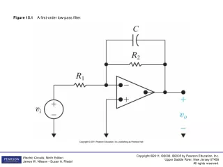
Second-order Butterworth Low-pass Filter. Minh N Nguyen. Characteristics of Butterworth Filter. Maximally flat magnitude response A pulse input shows moderate overshoot and ringing The attenuation is -3dB at the cutoff frequency. Multiple-feedback low-pass filter.

E N D
Second-order Butterworth Low-pass Filter Minh N Nguyen
Characteristics of Butterworth Filter • Maximally flat magnitude response • A pulse input shows moderate overshoot and ringing • The attenuation is -3dB at the cutoff frequency
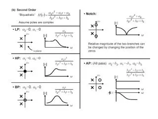
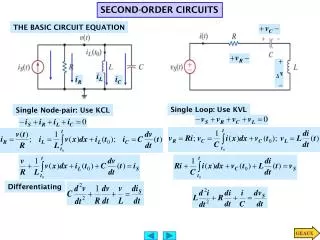
The form of 2nd low-pass filter T(S) = A0*ω0 ------------------------------------------------ s² + s(ω0/Q) + (ω0)^2
Transfer Function T(S) = - (G1G3/C2C5) ------------------------------------------------ s²+s[(G1+G3+G4)/C2]+(G3G4/C2C5)
Low-pass filter parameters • Open Loop DC Gain (Ao)of a low-pass filter. • Determining the values of Pole Frequency (fo) • Magnitude of the peaking relative to the DC Gain (Q)
Equations to calculate the parameters Ao = - (G1/G4) fo = (1/2pi) * [(G3/G4)/(C2C5)]^(1/2) Q = (1/(G1 + G3 + G4)) * [(G3G4C2)/C5]^(1/2)
Components Selection R1 = 81.98 kΩ R2 = 82.39 kΩ R3 = 38.77 kΩ C2 = 698 pF C5 = 136 pF 741 Op-Amp
Theoretical Calculations • G1 = 1/R1 = 1.21E-5 • C2 = 698E-12 • G3 = 1/R3 = 2.57E-5 • G4 = 1/R4 = 1.21E-5 • C5 = 136E-12
Theoretical Calculations(continue) Ao = - (G1/G4) = -1 fo = (1/2pi) * [(G3/G4)/(C2C5)]^(1/2) = 9.109 kHz Q = (1/(G1 + G3 + G4)) * [(G3G4C2)/C5]^(1/2) = 0.801