Download
1 / 24
431 likes | 1.46k Views
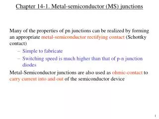
Semiconductor Device Physics. Chapter 14 MS Contacts and Schottky Diodes. Chapter 14. Metal-Semiconductor Contacts and Schottky Diodes. pn -junction diode. I. V A. Schottky diode. MS Contact. The metal-semiconductor (MS) contact plays a very important role in solid-state devices.

E N D
Semiconductor Device Physics Chapter 14 MS Contacts and Schottky Diodes
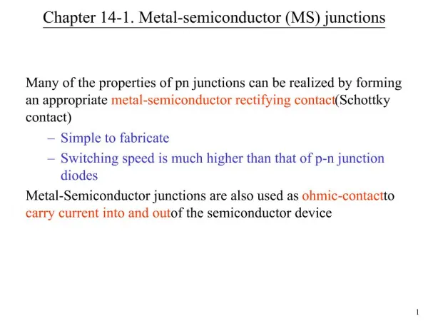
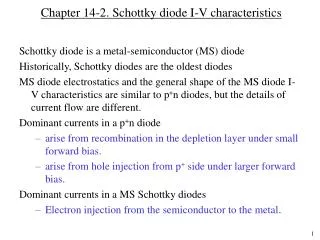
Chapter 14 Metal-Semiconductor Contacts and Schottky Diodes pn-junction diode I VA Schottky diode MS Contact • The metal-semiconductor (MS) contact plays a very important role in solid-state devices. • When in the form of a rectifying contact, the MS contact is referred to as the Schottky. • When in the from of a non-rectifying or ohmic contact, the MS contact is the critical link between the semiconductor and the outside. • The reverse-bias saturation current IS of a Schottky diode is 103 to 108 times larger than that of a pn-junction diode, depending on the type of material. • Schottky diodes are proffered rectifiers for low-voltage high-current applications.
Chapter 14 Metal-Semiconductor Contacts and Schottky Diodes MS Contact • A vacuum energy level, E0, is defined as the minimum energy an electron must possess to completely free itself from the material. • The energy difference between E0 and EF is known as the workfunction (Φ).
Chapter 14 Metal-Semiconductor Contacts and Schottky Diodes Workfunction E0: vacuum energy level cSi= 4.03eV FM: Metal workfunction FS: Semiconductor workfunction EFM: Fermi level in metal EFS: Fermi level in semiconductor c: electron affinity
Chapter 14 Metal-Semiconductor Contacts and Schottky Diodes Ideal MS Contact: FM >FS, n-type • E0 is continuous • Band diagram instantly after contact formation • Band diagram under equilibrium condition • Surface potential-energy barrier
Chapter 14 Metal-Semiconductor Contacts and Schottky Diodes Ideal MS Contact: FM <FS, n-type • E0 is continuous • Band diagram instantly after contact formation • Band diagram under equilibrium condition
Chapter 14 Metal-Semiconductor Contacts and Schottky Diodes n-type MS Contact • Current is determined by majority-carrier flow across the MS junction. • Under forward bias, majority-carrier diffusion from the semiconductor into the metal dominates. • Under reverse bias, majority-carrier diffusion from the metal into the semiconductor dominates. Forward Bias Forward bias Reverse bias Reverse Bias
Chapter 14 Metal-Semiconductor Contacts and Schottky Diodes I VA I VA Metal-Semiconductor Contacts • There are 2 kinds of metal-semiconductor (MS) contact: • Rectifying (“Schottky diode”) • Non-rectifying (“Ohmic contact”)
Ec Ec EF EF Ev Ev Ec Ec EF EF Ev Ev Metal-Semiconductor Contacts
Chapter 14 Metal-Semiconductor Contacts and Schottky Diodes The Depletion Approximation • The semiconductor is depleted to a depth W: • In the depleted region (0 x W ): • Beyond the depleted region (x > W ): Vbi : “built-in” voltage
Chapter 14 Metal-Semiconductor Contacts and Schottky Diodes Area A E(x) E(x+Dx) Dx Poisson’s Equation • According to Gauss’s Law: • Or: • E : electric field intensity (V/m) • S : relative permittivity (F/cm) • : charge density (C/cm3) • S = KS0 • 0 = 8.854 × 10⁻¹⁴ F/cm • For Si, KS = 11.8
Chapter 14 Metal-Semiconductor Contacts and Schottky Diodes + – MS Contact Electrostatics • Poisson’s equation: • The solution is: • Furthermore:
Chapter 14 Metal-Semiconductor Contacts and Schottky Diodes + – Depletion Layer Width W • The potential in the semiconductor side is chosen to be the zero reference. • At x = 0, V = –Vbi • The depletion width is given by • W decreases as ND increases
Chapter 14 Metal-Semiconductor Contacts and Schottky Diodes + – Depletion Layer Width W for VA 0 • Previously, • At x = 0, now V = – (Vbi– VA) • W decreases as ND increases • W increases as –VA increases – (Vbi–VA)
Chapter 14 Metal-Semiconductor Contacts and Schottky Diodes Thermionic Emission Current • Thermionic emission current results from majority carrier injection over the potential barrier. • Electrons can cross the junction into the metal if: • The current for electrons at a certain velocity is: • Or: • The total current over the potential barrier is:
Chapter 14 Metal-Semiconductor Contacts and Schottky Diodes I–VCharacteristics • For a non-degenerate semiconductor, it can be shown that: • We can then obtain • Where • And
Chapter 14 Metal-Semiconductor Contacts and Schottky Diodes I–VCharacteristics • In the reverse direction and equilibrium condition, the electrons always see the same barrier FB, so • Therefore –IS :reverse bias saturation current • Finally, combining the total current at an arbitrary VA, • Where
Chapter 14 Metal-Semiconductor Contacts and Schottky Diodes Small-Signal Capacitance • In an MS contact, charge is stored on either side of the MS junction. • The applied bias VA affects this charge and varies the depletion width. • If an a.c. voltage va is applied in series with the d.c. bias VA, the charge stored in the MS contact will be modulated at the frequency of the a.c. voltage. • Displacement current will flow.
Chapter 14 Metal-Semiconductor Contacts and Schottky Diodes Small-Signal Capacitance • Since in general • Then • Or
Chapter 14 Metal-Semiconductor Contacts and Schottky Diodes Practical Ohmic Contact • In practice, most MS-contacts are rectifying. • In order to achieve a contact that can conduct easily in both directions, the semiconductor is to be doped very heavily. • Depletion width W becomes so narrow that the carriers can tunnel directly through the barrier.
Chapter 14 Metal-Semiconductor Contacts and Schottky Diodes qVbi q(Vbi–VA) q(Vbi–VA) Voltage Drop Across the MS Contact • Under equilibrium conditions (VA = 0), the voltage drop across the semiconductor depletion region is the built-in voltage Vbi. • If VA 0, the voltage drop across the semiconductor depletion region is Vbi– VA.
Chapter 14 Metal-Semiconductor Contacts and Schottky Diodes MS Contact with p-type Semiconductor • If p-type semiconductor is used, the depletion layer width W of the MS contact for VA 0 is given by ? ? • At x = 0, V = Vbi+ VA, ? • W increases as VA increases • W decrease as NA increases
Chapter 14 Metal-Semiconductor Contacts and Schottky Diodes Homework 9 • 1.(Nea.EC.10.27) • An MS-junction is formed between a metal with a work function of 4.3 eV and p-type Si with an electron affinity of 4 eV. The doping concentration in semiconductor is 5×1016 cm–3. Assume T = 300 K. (a) Sketch the thermal equilibrium energy band diagram; (b) Determine the height of the Schottky barrier; (c) Sketch the energy band diagram with an applied reverse-bias voltage of VA = –3V; (d) Sketch the energy band diagram with an applied forward-bias voltage of VA = 0.25 V. • Due: 12.12.2013.