General Sequential Systems
COUNTERS Counters with I nputs Kinds of Counters Asynchronous vs. Synchronous Counters Cascaded Counters. D Q. D Q. Current State. State Memory. Next State. Input Forming Logic. General Sequential Systems. Counters.

General Sequential Systems
E N D
Presentation Transcript
COUNTERSCounterswithInputsKinds of CountersAsynchronous vs. SynchronousCountersCascaded Counters
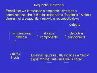
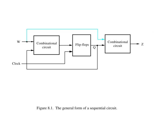
D Q D Q CurrentState StateMemory NextState InputFormingLogic General Sequential Systems
Counters • Counters are registers that go through a predefined sequence of states when inputs are applied • Many counters follow the binary number sequence • For example, a 3-bit binary ripple counter goes through the following state transitions when the clock is asserted: 000 → 001 → 010 → 011 → 100 → 101 → 110 → 111 → 000 … • Counters are said to overflow when their sequence is complete • Overflow causes counters to repeat a sequence of values over time Lecture Notes - SE 141: Digital Circuits and Systems
Types of Counters • Two types of counters exist: • Synchronous Counters • Ripple Counters Synchronous counters are triggered by a commonclock Ripple counters use flip-flop output transitions to serve as the trigger source for other flip-flops • For example, a 1 to 0 transition on flip-flopi triggers a toggling transition on flip-flopi + 1 Ripple counters are not triggered by a common clock Lecture Notes - SE 141: Digital Circuits and Systems
Synchronous Counters • In a synchronous counter, all flip flops are clocked by the same clock signal • They all change at the same time • Synchronous counters can be cascaded to create larger counters that are also globally synchronous
Transition Table for 2-Bit Counter It is the truth table for the input forming logic… It describes what the next state values are as a function of the current state (clock is assumed)
D Q D Q N1 Q1 CLK Q0 N0 CLK Implementation of 2-Bit Counter N0 = Q0’ N1 =Q1 Q0
D Q D Q N1 Q1 CLK Q0 N0 CLK Example 2 – A Gray Code Counter N1= Q0 N0 = Q1’
Example 3 – Not All Count Values Used Desired count sequence = 00 – 01 – 11 - 00 … What should next state for 10 be?
N1 = Q0•Q1’ N0 = Q0’ Example 3 – Not All Count Values Used Do the normal K-map minimization with don’t cares
T Q T Q T Q Counters With Alternative FF’s CurrentState StateMemory InputFormingLogic T Inputs
Counter Design Procedure Introduction The process is a special case of the general sequential circuit design procedure. no decisions on state assignment or transitions current state is the output Example: 3-bit Binary Upcounter Decide to implement with Toggle Flipflops What inputs must be presented to the T FFs to get them to change to the desired state bit? We need to use the T FF excitation table to translate the present/next state values to FF inputs Present state Next state 0 0 0 0 1 1 1 1 0 0 1 1 0 0 1 1 0 1 0 1 0 1 0 1 0 0 0 1 1 1 1 0 0 1 1 0 0 1 1 0 1 0 1 0 1 0 1 0 55:032 - Introduction to Digital Design
TFF Counter Design Using Augmented Transition Table Next state values Inputs to apply to achieve desired next state
TFF Counter Design Using Augmented Transition Table T2 T2 = Q1•Q0T1 = Q0T0 = ‘1’ Next state values Inputs to apply to achieve desired next state
T Q T Q T Q TFF Counter Design Q2 CLK Q1 CLK ‘1’ Q0 CLK
4-Bit Synchronous Binary Counter NOTE: This is a well-designed circuit. It can operate at high clock frequencies. The maximum clock frequency can be easily calculated. For high-speed digital design, synchronous binary counters are preferred. Lecture Notes - SE 141: Digital Circuits and Systems
JKFF Gray Code Counter Design Next state values Inputs to apply to achieve desired next state
JKFF Gray Code Counter Design J2 = Q1•Q0’K2 = Q1’•Q0’ J1 = Q2’•Q0K1 = Q2•Q0 J0 = Q2•Q1 + Q2’•Q1’ = K0’K0 = Q2’•Q1 + Q2•Q1’ = Q2 Q1 Next state values Inputs to apply to achieve desired next state
D Q D Q CurrentState StateMemory NextState InputFormingLogic OutputFormingLogic Outputs Counters With Outputs Outputs = f (CurrentState)
Counters With Outputs Z=1 when count={0,3,6} Z is called a Moore or static output. It is a function only of the current state.
Combined Transition Table Current state Next state Output Z = Q2’•Q1’•Q0’ + Q2’•Q1•Q0 + Q2•Q1•Q0’ (implement OFL with gates)
D Q D Q Counter With A Moore Output D Q N2 Q2 CLK N1 Z Q1 CLK N0 Q0 OFL IFL CLK
D Q D Q An Incrementable Counter CurrentState StateMemory NextState InputFormingLogic Inputs Note that the next state is a function of the input ‘INC’ as well as the current state.
Incrementable Counter Derivation Doing the KMaps for this results in: N1 N0 N1 = INC•Q1’•Q0 + INC’•Q1 + Q1•Q0’ N0 = INC’•Q0 + INC•Q0’ = INCQ0
Incrementable Counter Behavior CLK INC CurrentState 00 01 10 The counter increments on the clock edge only when INC is asserted
Counters With More Inputs CLR = INC = 0 No state transition CLR = 0 INC = 1 Counter Increments CLR = 1 INC = 0 Counter resets to ‘00’ CLR = 1 INC = 1 What should it do?
Counters With More Inputs CLR = INC = 0 No state transition CLR = 0 INC = 1 Counter Increments CLR = 1 INC = 0 Counter resets to ‘00’ CLR = 1 INC = 1 What should it do?
Precedence of INC vs. CLR? • Could do nothing • Could give INC precedence • Could give CLR precedence • Assume INC=CLR=1 will never occur You decide when you draw the transition table!
Case 1 – Do Nothing N1 N0 N1 = CLR’•INC•Q1’•Q0 + CLR’•INC’•Q1 + CLR•INC•Q1 + INC•Q1•Q0’ N0 = CLR’•INC’•Q0 + CLR•INC•Q0 + CLR’•INC•Q0’
Case 2 – Give INC Precedence N1 N0 N1 = INC•Q1’•Q0 + CLR’•INC’•Q1 + INC•Q1•Q0’ N0 = CLR’•INC’•Q0 + INC•Q0’
Case 3 – Give CLR Precedence N1 N0 N1 = CLR’•INC•Q1’•Q0 + CLR’•INC’•Q1 + CLR’•Q1•Q0’ N0 = CLR’•INC’•Q0 + CLR’•INC•Q0’
Case 4 – Assume INC=CLR=1Will Never Occur N1 N0 N1 = CLR’•INC’•Q1 + INC•Q1’•Q0 + CLR’•Q1•Q0’ N0 = CLR’•INC’•Q0 + INC•Q0’ What happens in the real circuit when INC=CLR=1? It depends on the final equations…
4-Bit Up-Down Binary Counter NOTE: The Up control signal has priority. If Up is asserted, the Down signal will not pass through the AND gate. Lecture Notes - SE 141: Digital Circuits and Systems
4-Bit Binary Counter with Parallel Load Lecture Notes - SE 141: Digital Circuits and Systems
A common 4-bit counter Synchronous Load and Clear Inputs Positive Edge Triggered FFs Parallel Load Data from D, C, B, A P, T Enable Inputs: both must be asserted to enable counting RCO: asserted when counter enters its highest state 1111, used for cascading counters "Ripple Carry Output" 74163 Synchronous 4-Bit Upcounter 74161: similar in function, asynchronous load and reset 55:032 - Introduction to Digital Design
74163 Detailed Timing Diagram 55:032 - Introduction to Digital Design
Self-Starting Counters Start-Up States At power-up, counter may be in any possible state Designer must guarantee that it (eventually) enters a valid state Especially a problem for counters that validly use a subset of states Self-Starting Solution: Design counter so that even the invalid states eventually transition to valid state S5 S6 S0 S4 S0 S4 S1 S3 S1 S3 S2 S2 S6 S7 S5 S7 Two Self-Starting State Transition Diagrams 55:032 - Introduction to Digital Design
+V +V +V \Reset 1 0 Q Q Q Q S S S S 1 2 3 4 J J J J Q Q Q Q CLK CLK CLK CLK K Q K Q K Q K Q R R R R Shift Twisted Ring (Johnson, Mobius) Counter Inverted End-Around 8 possible states, single bit change per state, useful for avoiding glitches +V 55:032 - Introduction to Digital Design
Q Q Q Q 1 2 3 4 100 Shift Q1 Q2 Q3 Q4 1 0 0 0 0 1 0 0 0 0 1 0 0 0 0 1 1 0 0 0 0 1 0 0 0 0 1 0 0 0 0 1 1 0 0 0 Ring Counter +V +V +V End-Around \Reset 1 4 possible states, single bit change per state, useful for avoiding glitches Must be initialized 0 S S S S J J J J Q Q Q Q CLK CLK CLK CLK K Q K Q K Q K Q R R R R Shift V+ 55:032 - Introduction to Digital Design
Binary Ripple Counter • Consider the following binary sequence: 000 001 010 011 100 101 110 111 000 Indicates a toggling of the 2nd least significant bit Indicates a toggling of the most significant bit Lecture Notes - SE 141: Digital Circuits and Systems
4-Bit Binary Ripple Counter Lecture Notes - SE 141: Digital Circuits and Systems
BCD Ripple Counter • It is possible to build counters that go through any fixed sequence of binary numbers • For example, a BCD ripple counter can be specified by the following state diagram: Lecture Notes - SE 141: Digital Circuits and Systems
4-Bit BCD Ripple Counter Lecture Notes - SE 141: Digital Circuits and Systems
12-Bit BCD Counter Lecture Notes - SE 141: Digital Circuits and Systems
Mod-N Counters • Generally we are interested in counters that count up to specific count values • Not just powers of 2 • A mod-N counter has N states • Counts from 0 to N-1 then rolls over • Requires flip flops • For example… • A 4-bit binary counter is a mod-16 counter • A counter that counts from 0-9 is a mod-10 counter
A Mod-4 CounterA.K.A. 2-bit counter CLR’•INC’ CLR 00 CLR’•INC CLR’•INC CLR’•INC’ CLR’•INC’ 11 01 CLR’•INC CLR’•INC 10 CLR’•INC’