Download

1 / 50
540 likes | 938 Views
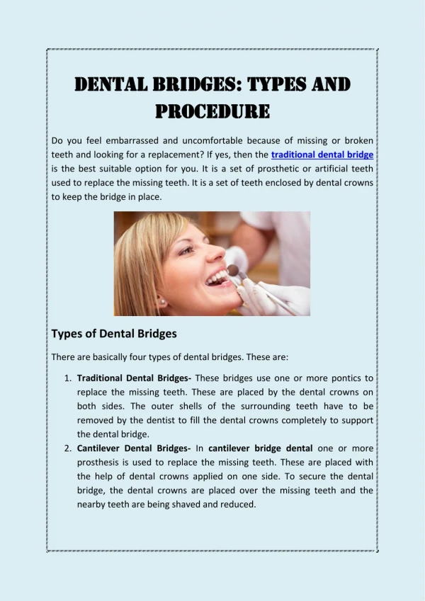
Dental bridges (pontics). Clinical and technological aspects.

E N D
Dental bridges (pontics). Clinical and technological aspects.
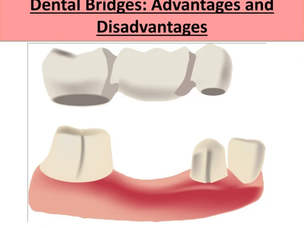
Careful planning is always necessary when deciding how to restore an undersized pontic space where orthodontic treatment is not practical. A, In this patient, individual crowns of increased proximal contours were preferred to an FPD with undersized pontics. Excellent plaque control had been demonstrated, and the design provided the optimum occlusal relationship. B, Here a small pontic (arrow) was preferred to splint an RPD abutment.
Loss of residual ridge contour leading to unesthetic open gingival embrasures (A) and food entrapment (arrow) (B)
Fig 3-2. Residual ridge deformities as classified by Siebert.2 A, B, Class I defect. C, Class П defect. D, Class III defect.
Fig. 3-3. The roll technique for soft tissue ridge augmentation. A, Cross section of Class I residual ridge defect before augmentation. B, Epithelium removed from palatal surface. C, Elevation of flap, creating a pouch on the vestibular surface. D, The flap is rolled into the pouch, enhancing ridge width.
Fig 3-4. The pouch technique for soft tissue ridge augmentation. A and B, Split-thickness flap is reflected. C, Graft material placed in the pouch increases ridge width. D, Flaps sutured in place.
Fig. 3-5.An interpositional graft for augmentation of ridge width and height. A, Tissue reflected. B, Graft positioned and sutured in place
Fig. 3-6. An onlay graft for augmentation of ridge width and height. A, Presurgical view of Class III residual ridge defect with abutment teeth prepared. B, Recipient bed prepared by removing epithelium. C, Striation cuts are made in connective tissue to encourage revascularization. D, Onlay graft is sutured in place. E, A provisional FPD with open embrasures is placed immediately to allow adaptation of tissue during healing. F, Presurgical view of Class ПІ residual ridge defect. G, The defect necessitated long, poorly contoured pontics. H, Augmented ridge. 1, Final restorations with improved contours. (Fto I courtesy Dr. H. Breckner.)
Fig. 3-7. Alveolar architecture preservation technique. A, Atraumatic tooth extraction. B, Cross-section view of the immediate provisional FPD demonstrating ovate pontic form. C, Provisional restoration. Note the 2.5-mm apical extension of the ovate pontic. D, The seated provisional should cause slight blanching of interdental papilla. E, Provisional restoration 12 months after extraction. Note the preservation of interdental papilla. (Courtesy Dr. E Spear and Montage Media.)
Fig. 3-8. A "hygienic" or "sanitary" pontic replacing a mandibular molar where there has been considerable bone loss.
Fig. 3-9. A, Sanitary pontic. B and C, Modified sanitary pontic. D, Placement of the pontic, close to the ridge, has resulted in tissue proliferation (arrow).
Fig. 3-10. A, Cross-section view of ridge lap pontic. B, The tissue surface is inaccessible to cleaning devices Fig. 3-11. a and B, FPD with a ridge-lap (concave) gingival surface. C, When it was removed, the tissue was found to be ulcerated. D, The defective FPD was recontoured and used as a provisional restoration while the definitive restoration was being fabricated. Within 2 weeks the ulceration had re-
Fig. 3-12. Modified ridge lap pontic. A, FPD partially seated. B, FPD seated.
Fig. 3-13. Three-unit FPD replacing the maxillary lateral incisor. A, To facilitate plaque control, the lingual surface is made convex. B, The facial surface is shaped to simulate the missing tooth.
Fig. 3-14. Tissue contact of a maxillary FPD should resemble the letter T. This FPD is viewed from the gingival aspect.
Fig. 3-15. A and B, A pontic with maximum convexity and single point contact of the tissue surface is the easiest design to keep clean. C, Evaluating the contour of three possible pontic shapes (1,2, and 3). Contour 3 is the most convex in area B but is too flat in area A. Contour 1 is convex in area A but is too flat in area B. Contour 2 is the best. D, An all-metal FPD with a conical pontic, suitable for replacement of a mandibular molar.
Fig. 3-16. A, Conical pontics may create food entrapment on broad residual ridges (arrow). B, The sanitary pontic form may be a better alternative.
Fig. 3-17. Ovate pontic. A, FPD partially seated. B, FPD seated
Fig. 3-18. The ovate pontic design eliminates the potential for unsupported porcelain in the cervical portion of an anterior pontic
Fig. 3-20. Soft tissue blanching at try-in indicates pressure.
Fig. 3-21. The patient must be instructed how to clean the gingival surface of a pontic with floss.
Fig. 3-22. Scanning electron micrographs of glazed porcelain (A), polished gold (B), and polished acrylic resin (C). (Microscopy by Dr. J.L. Sandrik.)
Fig. 3-23. Four pontic designs in descending order of strength based on cross sectional diameter of the metal substructure. When vertical space is minimal, design 4 (porcelain tissue and occlusal coverage) may be contraindicated.
Fig. 3-24. Failure of a long span metal-ceramic FPD subjected to high stress.
Fig. 3-25. Failure resulting from improper laboratory technique.
Fig. 3-27. A, Waxing to anatomic contour and controlled cut-back are the most reliable approaches to fabricating a satisfactory metal substructure (B).
Fig. 3-28. Failure caused by occlusal contact across the metal-ceramic junction.
Fig. 3-30. Correct incisogingival height is critical to esthetic pontic design. A, Esthetic failure of a four-unit FPD replacing the right central and lateral incisors. The pontics have been shaped to follow the facial contour of the missing teeth, but because of bone loss they look too long. B, The replacement FPD. Note that the gingival half of eachpontic has been reduced. Esthetics is much improved. C, This esthetic failure is the result of excessive reduction.The central incisor pontics look too short.
Fig. 3-31. Optical illusion. A and B are identical except that one image is upside down. Most people make different three-dimensional interpretations of each photograph, interpreting one as a negative impression and the other as a positive cast. (Verify the illusion by turning the book.) The interpretation is based on how shadows fall; in normal situations, objects are seen illuminated from above.
Fig. 3-32. A pontic should be interpreted as "growing" out of the gingival tissue. The second premolar pontic in the four-unit FPD (A) is successful because it is well adapted to the ridge; however, the pontic for the first premolar is evident because of its poor adaptation to the ridge, which creates a shadow. B, Shadows around the gingival surface (arrow) spoil the esthetic illusion. CORRECT INCORRECT
Fig. 3-33. A, A pontic should have the same incisogingival height (H) as the original tooth. B, Correctly contoured pontic. C, Incorrect contour. (The dotted lines in B and C show the original tooth contour.) The shelf at the gingival margin may trap food and create an estheti-cally unacceptable shadow. It is often necessary to recontour a substantial portion of the facial surface (B) to minimize a shadow or food trap at the heoriginal too th contou r.)
Fig. 3-34. It is difficult without surgical augmentation to fabricate an esthetic fixed prosthesis for a patient with extensive alveolar bone loss. A and B, One approach is to contour the crowns normally and shape and stain the apical extension to simulate exposed root surface. Better esthetics is obtainable withanRPD (C). (A and B redrawn from Blancheri RL: Rev Asoc Dent Mex 8:103, 1950.)
Fig. 3-35. Fixed partial denture replacing maxillary left central and lateral incisors. This patient had lost significant bone from the edentulous ridge. Appearance of the prosthesis was enhanced with the use of pink porcelain between the pontics to simulate gingival tissue. The patient has been able to maintain excellent tissue health through the daily use of SuperFloss.
Fig. 3-36. An abnormally sized anterior pontic space can be restored esthetically by matching the location of the line angles and adjusting the interproximal areas. Large (A) and small (B) pontic spaces. Dimension a should be matched in the replacement. (Redrawnfrom BlancheriRL: Rev Asoc Dent Mex 8:103, 1950.)
Form is compromised in the lesser visible half. Fig. 3-37.When replacing a posterior tooth (A), duplicate the dimension of the more visible mesial half of the adjacent tooth. Narrow (B) and wide (C) pontic spaces. (Redrawnfrom Blancheri RL: Rev Asoc Dent Mex 8:103, 1950.)
Fig. 3-38. A, Eight-unit FPD with porcelain facings. B and C, This three-unit posterior FPD has been fabricated by postceramic soldering of a metal-ceramic facing to conventional gold. D, Metal-ceramic FPD with a modified ridge lap pontic (canine) appears to emerge from the gingiva.
Waxing armamentarium Fig. 3-39
Prefabricated wax pontics. Fig. 3-40
Complete contour wax patterns. Fig. 3-42.
Fig. 3-42. Cut-back procedure for a three-unit anterior FPD. A, Delineating the porcelain-metal junction. B, The central incisor has already been cut back, and the pontic has been troughed. The canine is still at anatomic contour. C, A ribbon saw is used to section the connector.
Fig. 3-43. Metal substructure ready for airborne particle abrasion and oxidation.
Fig. 3-44. Failure of unsupported gingival porcelain.
Fig. 3-46. Porcelain application. A, Substructure ready for opaquing. B, Opaque application.C, Body porcelain application. D, A piece of moistened tissue paper (arrow) on the edentulous ridge.E, The porcelain after the first firing.