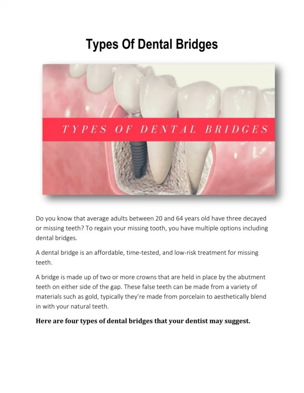
Download

1 / 45
680 likes | 2.13k Views
Indications, clinical and laboratory stages of manufacturing of swaged-soldered dental bridges. Clinical & laboratorial stages of swaged-soldered bridges making. Clinical stages. Laboratorial stages.

E N D
Indications, clinical and laboratory stages of manufacturing of swaged-soldered dental bridges
Clinical & laboratorial stages of swaged-soldered bridges making Clinical stages Laboratorial stages І. Patient examination. Diagnostics. Making of treatment plan. Preparation of abutment teeth. Taking impressions. І. Making of supporting crowns (swaging). ІІ. Fitting & trying on of supporting crowns. Taking of occlusal impression. ІІ. Modeling of intermediate (pontic) part of dental bridge. Molding of intermediate (pontic) part of dental bridge. Soldering of dental bridge parts. ІІІ. Fitting & trying ondental bridge framework. Choosing of veneer (facing) color. ІІІ. Modeling ofveneers (facing) with dental wax. Replacement of dental wax to acrylic resin. Polishing of dental bridge. ІV. Dental bridgefixation.
Making copy of gypsum stamp in low temperature molding alloy
Parker devise for external swaging(pressing) of artificial crowns
Stage of fitting & trying on of supporting crowns. б а а – checking of marginal adaptation with dental probe; б- visual examination with dental mirror.
Occlusal impression taking with gypsum. Applying gypsum Fixing of central occlusion Removing of occlusal impression Estimation of impression
Gypsum models are fixed to occludator than modeling of intermediate (pontic) part of dental bridge.
Final fitting of swaged-soldered bridge. Dental bridge after fixation.
Clinical & laboratorial stages of all metalic casted (molded) bridges making
Form is compromised in the lesser visible half. Fig. 3-37.When replacing a posterior tooth (A), duplicate the dimension of the more visible mesial half of the adjacent tooth. Narrow (B) and wide (C) pontic spaces. (Redrawnfrom Blancheri RL: Rev Asoc Dent Mex 8:103, 1950.)
Fig. 3-38. A, Eight-unit FPD with porcelain facings. B and C, This three-unit posterior FPD has been fabricated by postceramic soldering of a metal-ceramic facing to conventional gold. D, Metal-ceramic FPD with a modified ridge lap pontic (canine) appears to emerge from the gingiva.
Waxing armamentarium Fig. 3-39
Prefabricated wax pontics. Fig. 3-40
Complete contour wax patterns. Fig. 3-42.
Fig. 3-42. Cut-back procedure for a three-unit anterior FPD. A, Delineating the porcelain-metal junction. B, The central incisor has already been cut back, and the pontic has been troughed. The canine is still at anatomic contour. C, A ribbon saw is used to section the connector.
Fig. 3-43. Metal substructure ready for airborne particle abrasion and oxidation.
Fig. 3-44. Failure of unsupported gingival porcelain.
Fig. 3-46. Porcelain application. A, Substructure ready for opaquing. B, Opaque application.C, Body porcelain application. D, A piece of moistened tissue paper (arrow) on the edentulous ridge.E, The porcelain after the first firing.