Download
1 / 13
130 likes | 267 Views
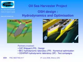
Oil Sea Harvester Project OSH design : Hydrodynamics and Optimisation. Partners involved : CAT Shipyard (FR) : Design BEC hydrodynamic laboratory (FR) : Numerical optimisation CEHIPAR hydrodynamic laboratory (SP) : Test campaigns. Transit phase

E N D
Oil Sea Harvester Project OSH design : Hydrodynamics and Optimisation Partners involved : • CAT Shipyard (FR) : Design • BEC hydrodynamic laboratory (FR) : Numerical optimisation • CEHIPAR hydrodynamic laboratory (SP) : Test campaigns
Transit phase Powering performances : relatively high transit speed Sea-keeping behaviour : low dynamic responses Oil recovery Phase Sea-keeping behaviour for oil recovery operations up to sea state 6/7 General Objective :Optimisation of the operational performances of the OSH concept
Objective : Light displacement (8000 t) Minimise the ship resistance at 25 knots Minimise all hydrodynamic interactionsat medium speeds Constraints : Pods integration (immersion of the transom stern) central cylindrical part of the main hull not modified Lateral distance between the side hull and the main hull not modified (toll carriage and oil recovery tool integration) Design parameters : Main hull Side hull Transit phase : powering optimisation
Bow sections : thinner waterline Buttock line and transom immersion Bulbous bow Powering optimisation : Main hull modifications Initial Final Initial form Initial Final Initial Final Optimal
Best length : 101m (initial) Best longitudinal location : fore Main hull AP FP Side hull 19 knots 25 knots 80 m Initialside hull Fore 101 m Aft 120 m 138 m Powering optimisation : Side hull modifications Best compromise between bow wave interactionsand stern wave interactions
Sea-keeping optimisation • Objective : sea-keeping performances • Transit phase : V ≈20 knots - = 8 000 t Tool carriage in folded position • Oil recovery operations : V : low speed = 12 000 t Tool carriage deployed • Constraints : • Pods integration • cylindrical part of the main hull not modified • distance between the side hull and the main hull not modified (tool carriage integration) • Design parameters : • Side hull • Tool carriage
Seakeeping optimisation for oil recovery operations (Transit phase not critical) • Increase of the side hull diameter : 3.5m (instead of 3m) • No influence of the longitudinal position of the side hulls • Optimal length of the tool carriage : 11.5m • Optimal location of the tool carriage : middle of the side hull Example of results : Influence of the length of the tool carriage on the oil recovery performances Operability diagram for 4 lengths : operability index (0-100%) versus wave heading
Optimal design • Thinner bow sections • Maximum transom immersion • (Bulbous bow) • Side hulls of length 101m at extreme fore location • Tool carriage of length 11.5m located in the middle of the side hull
Tank tests in progress (task 5.3)- assessment of the design optimised numerically - calibration of the numerical tools (re-used for the final design stage) • Resistance tests almost completed • Great importance of the static trim (transom immersion) • Optimal location of the side hull : fore Influence of the static trim • Seakeeping tests carried out from June to September 06 Influence of the longitudinal Side hull location
Statistiques du Golfe de Gascogne 71.8% 50 to 500 500 to 10 000 > 10 000 Quantity of oil spilled (tonnes) : Seakeeping optimisation • Definition of the operability value • Transit phase • Roll < 12° • Pitch < 4.5° • Vertical acceleration < 3m/s² • Oil recovery operations • Wave elevation < 1m • Relative heave < 3m • Vertical acceleration < 3m/s² • Maximum significant height • Operability diagramm
Seakeeping optimisationTransit phase • Better performances than in oil recovery operations • No need to optimise
Seakeeping optimisationOil recovery operations • Increase of the side hull diameter :3.5m • No influence of the longitudinal position of the side hulls • Optimal length of the tool carriage : 11.5m • Optimal location of the tool carriage : middle if the side hull Length of the tool carriage Lngitudinal location of the side hulls