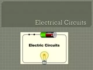

Electrical Circuits
E N D
Presentation Transcript
Series and Parallel Circuits Electrical Circuits
Key Ideas • In series circuits, the current passes through each component in turn. • In parallel circuits the current splits, some flowing through one branch, and some through another. • We can find a single resistor equivalent to these circuits. • Kirchhoff’s Laws can be used to analyse circuits
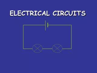
A I R1 R3 R2 V3 V1 V2 Series Circuit We know two things about this circuit: · All the voltages add up to the voltage given out by the battery. · The current is the same all the way round.
Therefore:Vtot = V1 + V2 + V3 • From Ohm’s Law we know: • Vtot = IRtot; V1 = IR1; V2 = IR2; V3 = IR3 • IRtot = IR1 + IR2 + IR3 • Rtot = R1 + R2 + R3 • This is true for any number of resistors in series.
Atot R1 I1 Itot A1 R2 I2 A2 R3 I3 A3 Parallel Circuit For a parallel circuit we know two things: · The voltage across each branch is the same · The currents in each branch add up to the total current.
Therefore Itot = I1 + I2 + I3 • From Ohm’s Law, I = V/R, we can write: • I tot = V ; I1 = V; I2 = V; I3 = V • Rtot R1 R2 R3 • V = V + V + V • Rtot R1 R2 R3 • 1 = 1 + 1 + 1 • Rtot R1 R2 R3 • This is true for any number of parallel resistors.
Kirchhoff’s Laws Kirchhoff I • I1 + I2 + - I3 = 0 • SI = 0 • The symbol S is Sigma, a Greek capital letter ‘S’, which means ‘sum of’. • The total current flowing into a point is equal to the current flowing out of that point. Kirchhoff II • Potential differences add up to the battery voltage. Electricity does not leak from wires!
E A C A I R1 R2 B V2 V1 Using Kirchhoff I & II Kirchhoff I I1 I3 I2 Kirchhoff II
Let us do a journey around the circuit from A to B to C, and back to A. · From A to B the p.d. drop is IR1 volts · From B to C the p.d. drop is IR2 volts · From C to A the pd. change is –E volts. If we add up all the voltages, we can write: IR1 + IR2 = E This is another way of saying that the voltages add up to the battery voltage.
Vs R1 Vout R2 0 V Potential Divider • In its simplest form it is two resistors in series with an input voltageVsacross the ends. • An output voltageVout is obtained from a junction between the two resistors.
If the output current is zero, the current flowing through R1 also flows through R2, because the resistors are in series. So we can use Ohm’s Law to say: • I = Vs • R1 + R2 • Now Vout = IR2 = Vs__ × R2 • R1 + R2 • Vout = R2___× Vs • R1 + R2 • This result can be thought of as the output voltage being the same fraction of the input voltage as R2 is the fraction of the total resistance. There is no need to work out the current.
Use of the Potential Divider The sound of silence Potential dividers are used in inputs to electronic circuits