Download
1 / 25
250 likes | 497 Views
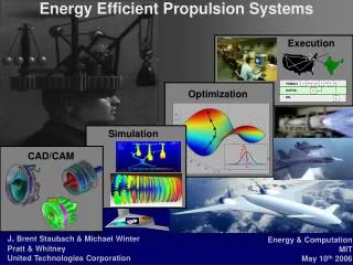
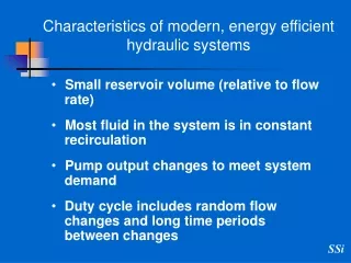
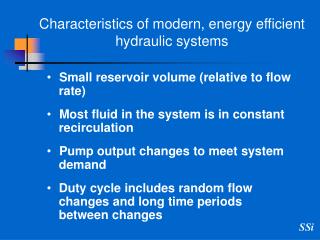
Small reservoir volume (relative to flow rate) Most fluid in the system is in constant recirculation Pump output changes to meet system demand Duty cycle includes random flow changes and long time periods between changes. Characteristics of modern, energy efficient hydraulic systems.

E N D
Small reservoir volume (relative to flow rate) Most fluid in the system is in constant recirculation Pump output changes to meet system demand Duty cycle includes random flow changes and long time periods between changes Characteristics of modern, energy efficient hydraulic systems
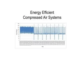
Increase in contamination level in the fluid (slug of contaminant released into the circuit by the filter) reaches all components in a relatively short time Typical time for the fluid to complete a full circuit from pump outlet to the pump inlet is 6 to 15 seconds
Average contamination levels relate to wear rates and mechanical failures. Maximum contamination levels cause operational failure. Operational failure occur when contamination levels exceed specified maximum values Sensitive components are at risk even if the are exposed to sort periods of exposure to increased level of contamination What is DFE and why we use it
Sensitive components will fail when their contaminant tolerance level is exceeded regardless of the length of time they operate in a clean environment
Filters need to be rated for their ability to control contamination levels and maintain it below the specified maximum, under all operating condition • Current filter ratings, other than DFE, are useful for comparing filters, to establish relative ranking, and are not designed to predict contamination levels in actual service
Filters capture some of the ingressed contaminants • Filters do notretain all of the captured contaminants
The Dynamic Filter Efficiency (DFE) test has been developed to measure contamination released (downloading) by the filter when exposed to flow changes Purpose of the DFE test
Variations in contamination levels are present during the duty cycle. Variations can exceed safe levels during normal operations. DFE is the test used to determine the maximum and the average contamination level a filter can control, in an operating system What is DFE and why we use it
Determines maximum contamination level in a system during the life of the filter under conditions simulating actual operations (Not an arbitrary laboratory test cycle) Provides accurate real time data of the contamination level in the fluid All test parameters are fully defined and under control throughout the test. Can be used for evaluating any size filter Can be used to evaluate a filter having any particle retention capability DFE Test
Automatic - operation is not affected by operator techniques Does not require experienced operators Does not require supporting laboratory facilities Gravimetric procedure Does not require additional test stands for testing filters Capacity Clean Flow DP Element collapse Fast, accurate, repeatable, economical Average test costs are a fraction of the cost of an ISO 16889 test Test report is printed at the conclusion of the test A new test can be started immediately after the completion of the previous test DFE Test System
Closed loop Recalculating (no bypass loop) Full flow trough filter Contaminant released is re circulated to the filter Same fluid throughout test (fluid is not introduced or removed during the test) Constant injection (rate relative to test flow) All the contaminant is either in the filter or suspended in the fluid Real time particle counting Dynamic APC flow control Self sufficient does not require experienced operators or additional test stands and laboratory facilities to complete a filter test DFE Test System cont.
Repeatability within the Test Lab on an identical Element (using the closed- loop Dynamic Filtration Efficiency Test Stand at SSI Labs)
Repeatability within the Test Lab on an identical Element (using the closed- loop Dynamic Filtration Efficiency Test Stand at SSI Labs)