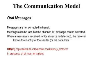
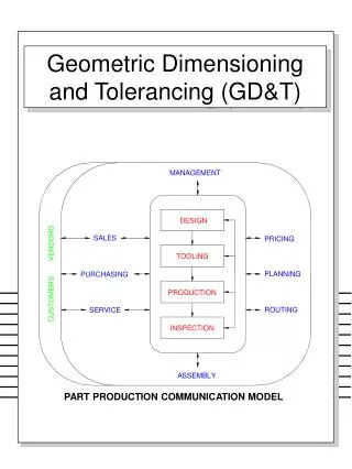
PART PRODUCTION COMMUNICATION MODEL
MANAGEMENT. DESIGN. SALES. PRICING. VENDORS. TOOLING. PLANNING. PURCHASING. PRODUCTION. CUSTOMERS. ROUTING. SERVICE. INSPECTION. ASSEMBLY. PART PRODUCTION COMMUNICATION MODEL. Geometric Dimensioning and Tolerancing (GD&T). Three Categories of Dimensioning.

PART PRODUCTION COMMUNICATION MODEL
E N D
Presentation Transcript
MANAGEMENT DESIGN SALES PRICING VENDORS TOOLING PLANNING PURCHASING PRODUCTION CUSTOMERS ROUTING SERVICE INSPECTION ASSEMBLY PART PRODUCTION COMMUNICATION MODEL Geometric Dimensioning and Tolerancing (GD&T)
Three Categories of Dimensioning Dimensioning can be divided into three categories: • general dimensioning, • geometric dimensioning, and • surface texture. The following provides information necessary to begin to understand geometric dimensioning and tolerancing (GD&T)
Geometric Dimensioning & Tolerancing (GD&T) • GD&T is a means of dimensioning & tolerancing a drawing which considers the function of the part and how this part functions with related parts. • This allows a drawing to contain a more defined feature more accurately, without increasing tolerances.
GD&T cont’d • GD&T has increased in practice in last 15 years because of ISO 9000. • ISO 9000 requires not only that something be required, but how it is to be controlled. For example, how round does a round feature have to be? • GD&T is a system that uses standard symbols to indicate tolerances that are based on the feature’s geometry. • Sometimes called feature based dimensioning & tolerancing or true position dimensioning & tolerancing • GD&T practices are specified in ANSI Y14.5M-1994.
For Example Assume all 4 legs will be cut to length at the same time. • Given Table Height • However, all surfaces have a degree of waviness, or smoothness. For example, the surface of a 2 x 4 is much wavier (rough) than the surface of a piece of glass. • As the table height is dimensioned, the following table would pass inspection. • If top must be flatter, you could tighten the tolerance to ± 1/32. • However, now the height is restricted to 26.97 to 27.03 meaning good tables would be rejected. or
.06 .06 .06 28 27 26 Example cont’d. • You can have both, by using GD&T. • The table height may any height between 26 and 28 inches. • The table top must be flat within 1/16. (±1/32)
WHY IS GD&T IMPORTANT • Saves money • For example, if large number of parts are being made – GD&T can reduce or eliminate inspection of some features. • Provides “bonus” tolerance • Ensures design, dimension, and tolerance requirements as they relate to the actual function • Ensures interchangeability of mating parts at the assembly • Provides uniformity • It is a universal understanding of the symbols instead of words
WHEN TO USE GD&T • When part features are critical to a function or interchangeability • When functional gaging is desirable • When datum references are desirable to ensure consistency between design • When standard interpretation or tolerance is not already implied • When it allows a better choice of machining processes to be made for production of a part
TERMINOLOGY REVIEW • Maximum Material Condition (MMC): The condition where a size feature contains the maximum amount of material within the stated limits of size. I.e., largest shaft and smallest hole. • Least Material Condition (LMC): The condition where a size feature contains the least amount of material within the stated limits of size. I.e., smallest shaft and largest hole. • Tolerance: Difference between MMC and LMC limits of a single dimension. • Allowance: Difference between the MMC of two mating parts. (Minimum clearance and maximum interference) • Basic Dimension: Nominal dimension from which tolerances are derived.
LIMITS OF SIZE A variation in form is allowed between the least material condition (LMC) and the maximum material condition (MMC). EnvelopPrinciple defines the size and form relationships between mating parts.
ENVELOPE PRINCIPLE LMC CLEARANCE MMC ALLOWANCE LIMITS OF SIZE
LIMITS OF SIZE The actual size of the feature at any cross section must be within the size boundary. ØMMC ØLMC
LIMITS OF SIZE No portion of the feature may be outside a perfect form barrier at maximum material condition (MMC).
Other Factors I.e., Parallel Line Tolerance Zones
TYPE OF TYPE OF FEATURE TOLERANCE FLATNESS INDIVIDUAL (No Datum Reference) STRAIGHTNESS FORM CIRCULARITY CYLINDRICITY INDIVIDUAL or RELATED FEATURES LINE PROFILE PROFILE SURFACE PROFILE PERPENDICULARITY ORIENTATION ANGULARITY PARALLELISM RELATED FEATURES (Datum Reference Required) CIRCULAR RUNOUT RUNOUT TOTAL RUNOUT CONCENTRICITY POSITION LOCATION SYMMETRY GEOMETRIC CHARACTERISTIC CONTROLS 14 characteristics that may be controlled CHARACTERISTIC SYMBOL
Characteristics & Symbolscont’d. • Maximum Material Condition MMC • Regardless of Feature Size RFS • Least Material Condition LMC • Projected Tolerance Zone • Diametrical (Cylindrical) Tolerance Zone or Feature • Basic, or Exact, Dimension • Datum Feature Symbol • Feature Control Frame
FEATURE CONTROL FRAME GEOMETRIC SYMBOL TOLERANCE INFORMATION DATUM REFERENCES COMPARTMENT VARIABLES THE RELATIVE TO OF THE FEATURE MUST BE WITHIN CONNECTING WORDS Feature Control Frame
Feature Control Frame • Uses feature control frames to indicate tolerance • Reads as: The position of the feature must bewithin a .003 diametrical tolerance zoneat maximum material condition relative to datums A, B, and C.
Feature Control Frame • Uses feature control frames to indicate tolerance • Reads as: The position of the feature must bewithin a .003 diametrical tolerance zoneat maximum material condition relative to datums A at maximum material condition and B.
The of the feature must be within a tolerance zone. The of the feature must be within a tolerance zone at relative to Datum . The of the feature must be within a tolerance zone relative to Datum . The of the feature must be within a zone at relative to Datum . The of the feature must be within a tolerance zone relative to datums . Reading Feature Control Frames
Placement of Feature Control Frames • May be attached to a side, end or corner of the symbol box to an extension line. • Applied to surface. • Applied to axis
Ø .500±.005 Placement of Feature Control Frames Cont’d. • May be below or closely adjacent to the dimension or note pertaining to that feature.
1.000 Basic Dimension • A theoretically exact size, profile, orientation, or location of a feature or datum target, therefore, a basic dimension is untoleranced. • Most often used with position, angularity, and profile) • Basic dimensions have a rectangle surrounding it.
Cylindricity Flatness Straightness Circularity Form Features • Individual Features • No Datum Reference
.003 .003 0.500 ±.005 0.500 ±.005 Form FeaturesExamples Flatness as stated on drawing: The flatness of the feature must be within .06 tolerance zone. Straightness applied to a flat surface: The straightness of the feature must be within .003 tolerance zone.
0.500 0.500 0.505 0.505 .003 M .030 1.010 0.990 Form FeaturesExamples Straightness applied to the surface of a diameter: The straightness of the feature must be within .003 tolerance zone. Straightness of an Axis at MMC: The derived median line straightness of the feature must be within a diametric zone of .030 at MMC.
Activity 13 • Work on worksheets GD&T 1, GD&T 2 #1 only, and GD&T 3 • (for GD&T 3 completely dimension. ¼” grid.)
Features that Require Datum Reference • Orientation • Perpendicularity • Angularity • Parallelism • Runout • Circular Runout • Total Runout • Location • Position • Concentricity • Symmetry
1.000 Datum • Datums are features (points, axis, and planes) on the object that are used as reference surfaces from which other measurements are made. Used in designing, tooling, manufacturing, inspecting, and assembling components and sub-assemblies. • As you know, not every GD&T feature requires a datum, i.e., Flat
Datums cont’d. • Features are identified with respect to a datum. • Always start with the letter A • Do not use letters I, O, or Q • May use double letters AA, BB, etc. • This information is located in the feature control frame. • Datums on a drawing of a part are represented using the symbol shown below.
A A A ASME ISO ANSI 1994 1982 Datum Reference Symbols • The datum feature symbol identifies a surface or feature of size as a datum.
Line up with arrow only when the feature is a feature of size and is being defined as the datum A OR A A ANSI 1982 ASME 1994 Placement of Datums • Datums are generally placed on a feature, a centerline, or a plane depending on how dimensions need to be referenced.
A Ø .500±.005 A Ø .500±.005 Ø .500±.005 Placement of Datums • Feature sizes, such as holes • Sometimes a feature has a GD&T and is also a datum
UP BACK LEFT 6 LINEAR AND 6 ROTATIONAL DEGREES OF FREEDOM RIGHT FRONT DOWN UNRESTRICTED FREE MOVEMENT IN SPACE TWELVE DEGREES OF FREEDOM
Example Datums • Datums must be perpendicular to each other • Primary • Secondary • Tertiary Datum
Primary Datum • A primary datum is selected to provide functional relationships, accessibility, and repeatability. • Functional Relationships • A standardization of size is desired in the manufacturing of a part. • Consideration of how parts are orientated to each other is very important. • For example, legos are made in a standard size in order to lock into place. A primary datum is chosen to reference the location of the mating features. • Accessibility • Does anything, such as, shafts, get in the way?
Primary Datum cont’d. • Repeatability For example, castings, sheet metal, etc. • The primary datum chosen must insure precise measurements. The surface established must produce consistent • Measurements when producing many identical parts to meet requirements specified.
FIRST DATUM ESTABLISHED BY THREE POINTS (MIN) CONTACT WITH SIMULATED DATUM A Primary Datum • Restricts 6 degrees of freedom
Secondary & Tertiary Datums • All dimension may not be capable to reference from the primary datum to ensure functional relationships, accessibility, and repeatability. • Secondary Datum • Secondary datums are produced perpendicular to the primary datum so measurements can be referenced from them. • Tertiary Datum • This datum is always perpendicular to both the primary and secondary datums ensuring a fixed position from three related parts.
SECOND DATUM PLANE ESTABLISHED BY TWO POINTS (MIN) CONTACT WITH SIMULATED DATUM B Secondary Datum • Restricts 10 degrees of freedom.
THIRD DATUM PLANE ESTABLISHED BY ONE POINT (MIN) 90° CONTACT WITH SIMULATED DATUM C MEASURING DIRECTIONS FOR RELATED DIMENSIONS Tertiary Datum • Restricts 12 degrees of freedom.
THIS ON THE DRAWING A MEANS THIS SIMULATED DATUM- SMALLEST PART CIRCUMSCRIBED CYLINDER DATUM AXIS Size Datum (CIRCULAR)