Download
1 / 41
490 likes | 873 Views
SAR System and Signals Part 1 EE880 Synthetic Aperture Radar. M. A. Saville , PhD Summer, 2012. Lesson Overview. Review radar concept & range equation Develop signal models for pulse-Doppler radar Review discrete time & bandwidth relations. Radar Concept Illustration. Scatterer.

E N D
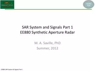
SAR System and Signals Part 1EE880 Synthetic Aperture Radar M. A. Saville, PhD Summer, 2012
Lesson Overview • Review radar concept & range equation • Develop signal models for pulse-Doppler radar • Review discrete time & bandwidth relations
Radar Concept Illustration Scatterer Transmit Line of sight Receive Line of sight Transmitter (ASR-9) Receiver Measure time it takes pulse to reach object and return to receiver (implies detection of the echo)
Radar Concept • RAdio Detection And Ranging (RADAR) • Send energy burst into environment • Transmit pulses of pulsewidthτ seconds • Periodically transmit a pulse every Tp seconds • Recover echoes (indicating presence of an object) • Threshold received energy and declare detection • Measure time to receive pulse since last transmission • Derive range R meters to object using speed of light • Radar range equation describes amount of energy returned – enables hardware trade studies
Radar Concepts – Timing & Sampling Signal Amplitude Run = Time (seconds) Signal Amplitude ΔR = Time (milli-seconds) Signal Amplitude Time (micro-seconds) Diagram to be completed during lecture
Radar Range Equation (RRE)(Conservation of power equation) • Ptx – transmit power • Gtx – transmit antenna gain • Grx – receive antenna gain • λ – wavelength • R – range to object • σ – radar cross section • Prx – receive power Prx= > Pmin Rmax= Speed of light in free space is c0 = 3.0x10⁸ m/s. Equations to be completed during lecture.
Basic Radar System Concept of Operation Transmitter(TX) TX Antenna Environment Targets Receiver(RX) Interference Clutter Database (DB) Receiver SignalProcessor (RSP) RX Antenna Display or Decision Maker (DM) Synchronizer (SYNC) See [Stimson] or [Sullivan] for more detail or alternate schematics
Example of Parametric Modeling Using RRE • Use the range equation to: • Design a monostatic air traffic control radar system to detect 1-m2 aircraft up to 80 nmi • Determine the “best” cost-performance solution Example worked during lecture
Basic Transmitter & Signals Transmitter gc(t) Coherent Oscillator gc(t) a∙ p(t) ∙ gc(t) s(t) Env Modulator Pre-Amplifier Power Amplifier p(t) Pulse Generator RX Receiver SignalProcessor (RSP) Database t, Tp, Fp, τ TX Ant Display or Decision Maker Synchronizer Signals to be developed in lecture.
Basic Transmitter Signals gc(t) = p(t) = s(t) = Signals to be developed in lecture.
Basic Radar Antenna Properties Antenna D G ≈ θHPBW ≈ Signals to be developed in lecture [Stimson, Sullivan].
Example – Range and Angle Discrimination • Determine the minimum separation distance needed to discriminate each case below Antenna Antenna ΔR = Case 1 R , Δθ Case 2 s = Signals to be developed in lecture.
Basic TX Antenna & “Signals” TX Ant s(t) = sTX(t) =
Basic Environment & “Signals” Concept of Operation s(t) sTX(t) TX Environment Space Loss TX Ant RX Ant Interference Targets Clutter Space Loss RT, σ RG, σ0 RJ,sjam Atmospheric Loss RX r(t) sRX(t) DB RSP DM SYNC
Basic Radar Physics in EnvironmentElectromagnetic (EM) Plane Waves • Spherical wavefront appears locally planar far from antenna (called the far field) Antenna Environment Planarmeans δβ< δSTX < δR δβ = D >> D Signals to be developed in lecture.
Basic Radar Physics in EnvironmentEM Scattering • EM waves are reflected (scattered), transmitted, or absorbed by objects (scatterers) in the environment • Scattering coefficient determines scattered power • Objects are assumed to be points in the basic system • Received power determined with radar range equation Incident Power Absorbed Power Transmitted Power Scattered Power
Basic Radar Physics in EnvironmentDoppler Frequency (1/2) • Relative motion between transmit (and receive) antenna and scatterers cause a frequency shift known as the Doppler Shift Ant β= fInstantaneous= fi= fDoppler= fD= Speed of light in free space is c0 = 3.0x10⁸ m/s. Equations to be completed during lecture.
Basic Radar Physics in EnvironmentDoppler Frequency (2/2) • Alternative view is time dilation / compression c0 >> v Time dilation – compression factor κ= F0’ is the apparent frequency which is simply F0’ = 1/T0’ Speed of light in free space is c0 = 3.0x10⁸ m/s. Equations to be completed during lecture.
Basic Environment “Signals” s(t) = sTX(t) = sRX(t) = r(t) = Signals to be developed in lecture.
Basic RX Antenna & “Signals” RX Ant sRX(t) = r(t) =
Basic Receiver & Signals Env Transmitter(TX) RX Ant gc(t) Receiver rI(t) rQ(t) Matched Filter Synchronous Detector Band-pass Filter Low-noise Amplifier Amplifier yI(t) yQ(t) r(t) Receiver SignalProcessor (RSP) Database t, Tp, Fp, τ Display or Decision Maker Synchronizer
Basic Receiver Signals rI(t) = rQ(t) = yI(t) = yQ(t) = Signals to be developed in lecture.
Basic Radar Signal Processing s(t) sTX(t) Concept of Operation TX Env TX Ant RX Ant RX r(t) sRX(t) Receiver Signal Processor(analog & digital shown) Digital Matched Filter d[n] MTD, STAP A/D yI(t) yQ(t) d[n] MTI Doppler Filter Bank Hypothesis Test A/D DB v(t) DM SYNC
Basic Digital Radar Signal Processing Signals v(t) = d[n] = Signals to be developed in lecture.
Basic Displays & Decision Making A-Scope (range versus amplitude) B-Scope (Planned Position Indicator ) Amplitude Range versus Angle Range • Information is displayed • Decision can be made by a human interpreter of data or automatically by a computer algorithm
Basic Radar System and Signals Concept of Operation sTX(t) s(t) TX TX Ant gc(t) Env r(t) sRX(t) RX RJ, sjam RT, σ RG, σ0 yI(t) yQ(t) d[n] DB RSP RX Ant t, Tp, Fp, τ DM SYNC
Topics in Radar Signal Processing • Detection • High range resolution (HRR) • Moving target detection • Airborne moving target indication • Adaptive clutter suppression • Tracking • HRR • Velocity (high velocity discrimination) • Angle • Radar imaging
Detection of Signals in Noise • Assuming a matched filter precedes the ADC s(t) = ), m = 0, 1,…,M-1 • Output of matched filter and sampling y(t) = Amplitude y[n] = Time ΔT = τ
Radar Ambiguity Function • Determines the energy in a range cell • Accounts for mismatch in time and Doppler Time Delay Time Delay Frequency mismatch Frequency mismatch Ambiguity function of unmodulated rectangular pulse Graphics made with MATLAB code from [Levanon]
Wide Band Signals • Commonly used pulses have frequency or phase variation within the pulse • Chirp or Costas code schirp(t) = • Barker code Signals to be developed in lecture.
High Range Resolution • Range bins (or cells) Uncompressed pulse Compressed pulse Amplitude Time τ/ρ τ • Radar can resolve very closely spaced objects • Depends on bandwidth: B ≈ 2/τ(unmodulated pulse) • Common compressed pulse has bandwidth Bcand pulse compression ratio ρ = Bc/B
Radar Ambiguity Function Graphics made with MATLAB code from [Levanon]
Velocity Detection and Discrimination • Doppler filter banks Amplitude … Frequency 0 -ΔF (M-1)ΔF ΔF ΔF ΔF = Δv =
Topics in Modern Radar • Phased array and multi-channel radar • Waveform diversity • Networked, distributed, layered sensors • Object detection and classification • Imaging with synthetic aperture radar Preponderance of topics involve advanced radar signal processing.
Digital Processing • Discrete Fourier Transform • Transform fast-time (intra-pulse sampling) or slow-time (inter-pulse sampling) samples to frequency domain F t F F-1 D nΔT qΔF D-1 • Often implemented with Fast Fourier Transform
Range-Frequency Transforms • Following matched filter • Range is time scaled by speed of light r =ct/2 • Discrete time samples ΔT are same as range bins ΔR • Range bin size is inversely proportional to signal bandwidth Range extent NΔR Record length NΔT Discrete Range (nΔR) Discrete Time (nΔT)
Range-Frequency Transforms • Transforming real-valued time samples • Results in sampled frequency spectrum with unambiguous region Fs/2, where Fs = 1/ΔT • Frequency spacing is inversely proportional to range extent Unambiguous spectrum NΔF=Fs/2 Spreading of single tone Discrete Spectrum (nΔF) Discrete Spectrum (nΔF)
Detection and Ranging • Range cell & Doppler bin thresholding • Matched filter every range cell • Doppler process the CPI for every range cell M Doppler bins Uncompressed range cell L range cells Compressed range cell
HRR in SAR Imaging • Antenna beam and pulse width determine scene extent • Image one uncompressed range cell • HRR waveform provides range resolution • Azimuth resolution in next lesson
Summary of SAR Systems & Signals Part 1 • Radar Concept • Radar Range Equation • Radar System • Concept of Operation • Transmitter • Receiver • Environment • Receiver Signal Processor • Antennas • Displays • Syncronization • Radar Signal Modeling • Signal processing for detection and estimation • Doppler processing for velocity detection and estimation • Discrete Fourier Transform relationships
Lesson References • [Levanon] N. Levanon, Radar Signals, Wiley-IEEE Press, 2004. • [Stimson] G. Stimson, Introduction to Airborne Radar, SciTech Publishing Inc., 1998. • [Sullivan] R. Sullivan, Foundations for Imaging and Advanced Concepts, SciTech Publishing Inc., 2004.