Download
1 / 36
360 likes | 454 Views
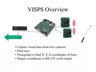
The Visual Laser Tracker System (VISPS) captures data from two cameras to locate a laser and determine X, Y, Z coordinates. The system outputs coordinates via RS-232 serial protocol for easy integration. VISPS achieves high accuracy using triangulation and logical implementation without complex math. The design ensures simplicity, accuracy, and ease of use for locating laser markers in a known reference frame. Various design elements and analysis contribute to fulfilling goals while addressing potential error sources. Lab results confirm the system's effectiveness with minor remaining issues to resolve.

E N D
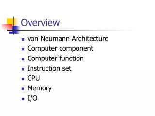
VISPS Overview RS-232 Out • Capture visual data from two cameras • Find laser • Triangulate to find X, Y, Z coordinates of laser • Output coordinates to RS-232 serial output
Talk Overview • VISPS goals and requirements – Cephas • Design (Theory + Architecture) – Steve • Design (Details + Communication) – Cephas • Design analysis – Kevin • Issues and testing – Kevin • Schedule – Cephas • Conclusion – Cephas
VISPS Purpose GOAL • Produce X, Y, Z coordinates of laser marker relative to known reference frame Requirements, use: • 630-680nm laser pointer • 2 RC-2 black and white cameras • XSV300 Development Board • PIC Microcontroller
High Level Design Goals • Produce X, Y, Z from visual data • Simple interface • Easy to use • General, Accurate • Design headroom
Parameter Value Coordinate Accuracy @ 63 inches the coordinates will be within 0.1 inches of its true location. Data Output RS-232 Protocol (19.2 Kbps / 8 data bits / 1 stop bit / no parity) Voltage Requires 9 and 12 V supply Maximum Operating Distance 60 feet Laser Flare Wavelength 630-680 nm Laser Flare Max Output < 1 mW Requirements Table 3 – VISPS operating parameter
Constraints From Requirements • Code size on PIC C < 20kB • Enough pins on XSV300 for two cameras input and communication with PIC C
How Are Design Goals Achieved? • Mathematics and theory • Logical implementation and architecture • Implementation details and subsystem communication
Triangulation Problem Summary Top View Side View
Visual Data Left Camera Right Camera Pixel coordinates are available.
Pixel Distances • h is a constant 340 pixels at any distance
Math And Theory Summary • Y, and Z found Similar to X • Found X, Y, and Z using in terms of pixel coordinates • No trigonometry or complex math • No multiplication of error
Design Implementation • Goals (Output points at 30fps, Preserve design headroom) • Black Box design outline • Component design specifics and I/O details
Generic Red Filters • Remove non-laser light VISPS RS-232 Coordinate output • PIC µC • Compute angles from pixel data • Compute X, Y, Z from angles • Output coordinates using RS-232 protocol • RoboCam RC-2 • Deliver pixel data • XSV300 • Locate Marker in pixel data • Generic Laser Pointer • Project marker
Finding Center Of Marker First saturated point Average of coordinates Last saturated point
BUSY C1hi C1lo C2hi C2lo Rhi Rlo DATA XSV300-PIC Protocol NEW READY
Design Analysis • Goals met • Requirements satisfied • Error analysis • Lab results
Goals Met • The design will correctly produce X, Y, and Z coordinates. • We managed to avoid solutions that would have made using VISPS overly cumbersome or complicated. • VISPS can output points at a full 30 points per second, the same rate as the camera • Significant upgrades to VISPS accuracy from higher resolution cameras would not require a major design change
Requirements Satisfied • Reworking our math enabled us to fit all the needed code on the PIC C • With current cameras, VISPS is accurate to within 0.1 inches at 60 inches • Moving to XSV300 from XS40 gave us the extra I/O pins we needed
Error Sources and Analysis • Miscalibration of cameras • Camera alignment • Camera leveling • Camera resolution • Output resolution
Miscalibration Of Cameras • All our mathematics are based on initial measurements at Z = 160cm • Introduction of systematic error in Z if h does not really equal 340 pixels • Spend extra time taking careful measurements • Integer value for h is encouraging • Do sanity checks against manual measurements
Camera Alignment • All our mathematics are based on the assumption that the two cameras are perfectly parallel • Introduction of systematic error if cameras are not parallel • Measure D at a distance check
Camera Leveling • To know the reference frame for the X, Y, Z values produced, camera assembly must be perfectly leveled • Use bubble levels mounted on camera assembly • Do sanity checks against manual measurements
Camera Resolution • Pixel size increases with distance • Error is equal to ½ pixel width as a function of Z • This error is inherent in VISPS and cannot be reduced except by increasing camera resolution • Not bad. Even at 340ft, error only = 5.5 inches!
Output Resolution • Output is in tenths of inches • Not a factor after 63 inches • This error is inherent in VISPS • Error can be reduced by reducing the max output distance
Lab Results • Cameras filtered with red filter produce good, noise free data • Able to find laser marker quickly, accurately, and consistently • PIC C output shows that math is correct • Unable to test system accuracy until parts are integrated
Problem Areas and Testing • Resolved issues • Remaining issues • Reviewers comments • Testing
Resolved Issues • Noise filtering • Interfering light sources • Complex math and PIC C memory constraints
Remaining Issues • Porting FPGA design to XSV300 • System accuracy
Testing • Do lots of sanity checks against manual measurements • Test validity of math theories • Visually inspect VGA output of laser finding module and camera perspective • Logic analyzer to check FPGA output • Extra PIC C test environment for PIC C • View serial output on Microsoft Hyperterminal • Output using printf() to test X, Y, Z production independently of coordinate output protocol
Current Status And Roadmap Port FPGA Design to XSV300. Completed: • Find laser in visual data • Module to talk to PIC C • PIC C math • PIC C, FPGA and RS-232 I/O Remaining • Port FPGA design to XSV300 • Integrate components and test • Win32 App for demo Week 8 Integrate Components, test, and debug. Week 9 More debugging, test, demo. Week 10 VACATION
Conclusion And Summary • Our design will work • Design goals are met