Download
1 / 11
110 likes | 229 Views
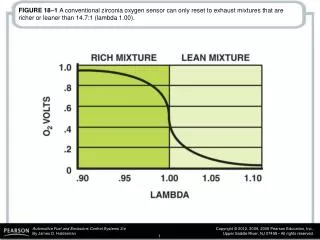
FIGURE 18–1 A conventional zirconia oxygen sensor can only reset to exhaust mixtures that are richer or leaner than 14.7:1 (lambda 1.00).

E N D
FIGURE 18–1 A conventional zirconia oxygen sensor can only reset to exhaust mixtures that are richer or leaner than 14.7:1 (lambda 1.00).
FIGURE 18–2 (a) When the exhaust is lean, the output of a zirconia oxygen sensor is below 450 mV. (b) When the exhaust is rich, the output of a zirconia oxygen sensor is above 450 mV.
FIGURE 18–3 Most conventional zirconia oxygen sensors and some wide-band oxygen sensors use the cup-type design.
FIGURE 18–4 A typical heated zirconia oxygen sensor, showing the sensor signal circuit that uses the outer (exhaust) electrode as negative and the ambient air side electrode as the positive.
FIGURE 18–5 A planar design zirconia oxygen sensor places all of the elements together, which allows the sensor to reach operating temperature quickly.
FIGURE 18–6 The reference electrodes are shared by the Nernst cell and the pump cell.
FIGURE 18–7 When the exhaust is rich, the PCM applies a negative current into the pump cell.
FIGURE 18–8 When the exhaust is lean, the PCM applies a positive current into the pump cell.
FIGURE 18–9 Testing a dual cell wideband oxygen sensor can be done using a voltmeter or a scope. The meter reading is attached to the Nernst cell and should read stoichiometric (450 mV) at all times. The scope is showing activity to the pump cell with commands from the PCM to keep the Nernst cell at 14.7:1 air–fuel ratio.
FIGURE 18–10 A single cell wide-band oxygen sensor has four wires with two for the heater and two for the sensor itself. The voltage applied to the sensor is 0.4 volt (3.3 - 2.9 = 0.4) across the two leads of the sensor.
FIGURE 18–11 The scan tool can display various voltage but will often show 3.3 volts because the PCM is controlling the sensor by applying a low current to the sensor to achieve balance.