Download
1 / 18
180 likes | 205 Views
Explore the journey of the LIGO Laser Interferometer Gravitational-wave Observatory, the principles of General Relativity applied to interferometers, past achievements, future goals, technical details such as seismic isolation, optics, sensing, and control mechanisms, as well as ongoing improvements for increased sensitivity and reliability.

E N D
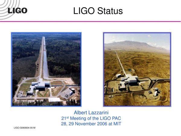
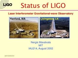
Status of LIGO Laser Interferometer Gravitational-wave Observatory Hanford, WA Livingston, LA Nergis MavalvalaMITIAU214, August 2002
Michelson Interferometer DL = h L h ~ 10-21 Pirani ‘56, Gerstenshtein and Pustovoit, Weber, Weiss ’72 Gravitational wave Interferometers: the principle General Relativity (Einstein 1916) predicts freely propagating transverse space-time distortions IAU214 - August 2002
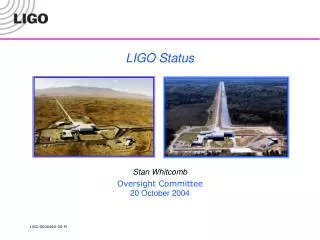
Initial Advanced Why an Observatory? • Two sites • Three interferometers • Coincidence • Long lifetime • Facilities limits • First detector (LIGO I) • Now • This talk • Advanced detectors (LIGO II and beyond) • 2006++ IAU214 - August 2002
Past…Future IAU214 - August 2002
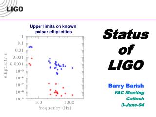
Initial LIGO Sensitivity Goal • Strain sensitivity < 3x10-23 1/Hz1/2at 200 Hz • Displacement Noise • Seismic motion • Thermal Noise • Radiation Pressure • Sensing Noise • Photon Shot Noise • Residual Gas • Facilities limits much lower IAU214 - August 2002
Vacuum 20 kW 10 W Laser 4 km 300 W Input Optics Detector Overview IAU214 - August 2002
Seismic Isolation • Seismic isolation stacks • Stainless steel masses 600 kg each stage • Helicoil springs with lossy viscoelastic layer Q ~ 40 • 3 to 4 stages 10-6 to 10-8 for f > 10 Hz IAU214 - August 2002
Core Optics • 25 cm diameter, 10 kg fused silica optics • Polished substrates • Micro-roughness < 10 ppm scatter • Optical coatings • < 2 ppm scatter • < 1 ppm absorption • Metrology • Surface uniformity~1 nm rms IAU214 - August 2002
Suspensions • Single wire loop suspensions • Four electromagnetic actuators • Four ‘shadow’ sensors for local position sensing Small optic Large optic IAU214 - August 2002
Optical Design of the Interferometers Requires test masses to be held in position to 10-10-10-13 meter: “Locking the interferometer” Light bounces in arm cavities ~130 times a increased phase sensitivity Light is “recycled” ~30 to 50 times InputOptics Laser Dark fringe signal IAU214 - August 2002
Interferometer Sensing and Control Pre-Mode Cleaner Laser IAU214 - August 2002
Engineering Run 7 (E7): LIGO + GEO + ALLEGRO IAU214 - August 2002
Strain Sensitivity during E7 IAU214 - August 2002
Evolution of strain sensitivity Major improvements • Front-end electronics (ADC) noise whiten signal • Laser frequency noise common-mode servo • Output electronics (DAC) noise whiten signal • Sensing electronics noise increase light level IAU214 - August 2002
All three interferometers locked for hours at a time in power-recycled configuration a Grec ~ 15 – 45 Lock acquisition is done using sys id methods a MTTL ~ 1 – 2 minute Optical parameters consistent with lab metrology a mirror losses < 70 ppm Tidal feedback systems operational a range of 200 mm pk-pk Mechanical (internal) modes of test masses excited a 104 < Q < 107 Laser input power 1 – 5 W but all light power not detected (PD saturations) Coupling to environment, e.g. Aircrafts flying by can be seen (heard?) Earthquakes Trains twice a day at Livingston Anthropogenic noise LIGO I Status Summary: What works IAU214 - August 2002
Seismic pre-isolation system At LLO 10x reduction in rms displacement of optics desired Active sensing and piezoelectric actuation system installed Hydraulic actuation prototyping underway for installation in 2003 Digital controls for optics suspension systems Greater flexibility for tuning servos Easier to orthogonalize displacement and angles of optic Installed/tested on Hanford 4km L4k, e.g., limited by coil driver noise at low frequencies Alignment control systems Partially operational (feedback loops closed on 2 – 4 of 12 degrees of freedom) Necessary to reduce spurious signals at AS port that causes photodiode saturations Increase detected light levels overcome sensing noise at high frequencies Electronics improvements New system layout being designed (EMI/RFI mitigation) Lower noise A/D converters LIGO I Status Summary:What doesn’t (yet) IAU214 - August 2002
The Task Ahead • Engineering runs • Characterize and improve detector sensitivity and reliability • Exercise data analysis system end-to-end pipeline • Science runs • Upper limits (E7 and beyond) • Scientific searches (S1 begins 08/23/02) • Commissioning remaining subsystems • Factor of 100 (above 400 Hz) to 100000 (at 40 Hz) improvement needed to reach design sensitivity • LIGO II R&D already underway IAU214 - August 2002
Detection Strategy: Coincidences • Two sites – three interferometers • Single interferometer 50/hr (non-gaussian level) • Hanford 4km + 2km 1/day (correlated rate) • Hanford + Livingston 0.1/yr (uncorrelated) • Data recording (time series) • Gravitational wave signal = 0.2 MB/sec • Total data = 16 MB/sec • On-line filters, diagnostics, data compression • Off-line data analysis, archiving… • Signal extraction • Signal from noise (vetoes, noise analysis) • Templates, wavelets… IAU214 - August 2002