FPGA-based Wireless Robotics Controller for Evolutionary Design
170 likes | 376 Views
FPGA-based Wireless Robotics Controller for Evolutionary Design. Conor Doyle Supervisor: Dr. Fearghal Morgan. Introduction.

FPGA-based Wireless Robotics Controller for Evolutionary Design
E N D
Presentation Transcript
FPGA-based Wireless Robotics Controller for Evolutionary Design Conor Doyle Supervisor: Dr. Fearghal Morgan
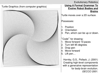
Introduction • The focus of this project is to develop a wireless interface between a 68HC11 (Handy board) microcontroller and a Virtex II pro FPGA containing a powerpc processor. The objective of this project is to create a fully autonomous robot that is controlled by an evolved controller contained on the Virtex II FPGA.
The Handy Board • The handy board is used to interface with the sensors and motors of the robot • The core of the handy board is a motorola 68HC11 micro processor. • The analog outputs of the sensors are converted to a 8 bit digital word by the micro-processor. This 8-bit value is then sent to the FPGA via the wireless link.
Wireless Link • The wireless link is implemented using a radiometrix RPC (Radio Packet control). • The RPC module provides all the RF circuits required to inter-connect an number of micro-controllers in a radio network.
Radiometrix RPC • A data packet of 1 to 27 bytes downloaded by a Host micro-controller into the RPC's packet buffer is transmitted by the RPC's transceiver and will "appear" in the receive buffer of all the RPC's within radio range. • A data packet received by the RPC's transceiver is decoded, stored in a packet buffer and the Host micro-controller signalled that a valid packet is waiting to be uploaded.
Pin Functions The Radiometrix RPC has 8 pins, 4 data lines and 4 control lines: • D0 – D3: 4 bi-directional data lines • TXR: TX request. Data transfer request from HOST to FRPC2 • TXA: TX Accept. Data accept handshake back to HOST • RXR: RX Request. Data transfer request from FRPC2 to HOST • RXA: RX Accept. Data accept handshake back to FRPC2