Impressed Current Interference
Impressed Current Interference. Western Regional Gas Conference 2008 Tempe, Arizona By Paul Sedlet, Accurate Corrosion Control, Inc. Summary of Presentation. Definition of impressed current interference Identification of stray current influence Testing and documenting interference

Impressed Current Interference
E N D
Presentation Transcript
Impressed Current Interference Western Regional Gas Conference 2008Tempe, ArizonaBy Paul Sedlet, Accurate Corrosion Control, Inc.
Summary of Presentation • Definition of impressed current interference • Identification of stray current influence • Testing and documenting interference • Consideration during new pipeline design • Coatings • Shielding • Test/Bond facilities • Solutions for interference • Bonding (Two Examples) • Magnesium Anodes (One Example) • Texas method
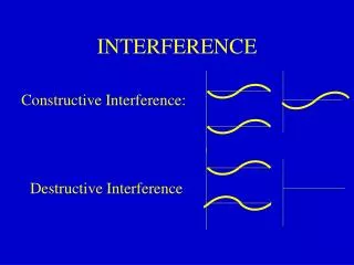
Definition of Impressed Current Interference • From NACE SP 0169 definitions • Interference: Any electrical disturbance on a metallic structure as a result of stray current. • Impressed Current: An electric current supplied by a device employing a power source that is external to the electrode system. (An example is direct current for cathodic protection.) • Stray Current: Current through paths other than the intended circuit.
Identification of Interference • Note areas of unexpectedly low potentials during monitoring. • Identify potential sources of stray impressed current (could be same Company if the systems are isolated). • While monitoring the low potential, measure the change in potential when the suspected source is interrupted; measure foreign current on your pipeline; measure potential gradients. • Look at big picture to identify and test for pick-up and discharge areas.
Design to Reduce Interference • Location • Proximity to existing foreign groundbeds • Consideration of others when locating new groundbeds • Coatings • Coating potential current pickup areas • Shielding or Non-Conductive Barriers • Physical barriers between pipelines at crossings • Test and Bond Facilities • Wires and soil tubes installed during construction
Example 1- Using CIS to Identify Possible Suppression, Waveform Testing to Identify Suppressing Operators and Bonding as a Solution
Example CIS- Possible Suppression Identified at MP 18 plus 147-feet
Investigation of above location Using Waveforms (Influence Study)
Example 2- Using Waveforms to Investigate Low Potentials at a Leak Site with Bonding Solution
P/S Waveform at Leak Site with Resist Bond Only to Foreign Operator
P/S Waveform at Leak Site with Full Bond to Foreign Operator
Using Waveforms to Indentify Suppression from Various Operators at Leak Site
Close Interval Waveforms (50ft) to Identify Scope of Suppressed Area
CI Waveforms Used to Indentify Specific Suppression from Foreign Operators
Example- Gas and Water Line Crossing with Magnesium Anode Interference Solution
N Gas Line 84” PCCP Pipeline Example- Magnesium Anode Installation at Crossing Anodes Terminated to Water Company to provide low resistant electrolytic path of Gas Co. current back to Gas Co. Pipeline • Legend • Gas Line Soil Tube • Water Line Soil Tube • Test Station/Anode Termination • #32 Magnesium Anode
Magnesium Anode Interference Solution Configuration Gas Co. CP Current
Example- Magnesium Anodes at Crossing DATA Pipe-to-soil potentials at crossing using new soil tubes 3-23-07 3-23-07 5-10-07 Wire Code As-Found (volts) As-Left (volts) Follow Up (volts) Water Co. White Tape -0.076 -0.661 -.850 I/O -.570 Gas Co. Yellow Tape -0.800 -1.143 -1.480 Mag. Anodes Red #14 -1.642 600mA 675mA Note: Cycling Rectifier (3-23-07)- Gas Co. Rectifier ON- Magnesium anodes output 590mA Gas Co. Rectifier OFF- Magnesium anodes output 238mA The data indicates approximately 352mA of Gas Co. current returning through the magnesium anodes back to the Gas Co.