Download
1 / 7
70 likes | 101 Views
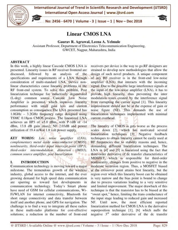
In this work, a highly linear Cascode CMOS LNA is presented. Linearity issues in RF receiver frontend are discussed, followed by an analysis of the specifications and requirements of a LNA through consideration of multi standard LNA. Device non linear characteristics cause linearity problems in the RF front end system. To solve this problem, Post linearization technique for inductively degenerated L deg common source Cascode Low Noise Amplifier is presented, which improves linearity performance with small gain loss and current consumption as consequence.The LNA presented has 1.0GHz 3.2GHz frequency range designed using TSMC 0.18u00b5-m CMOS process. The linearized LNA achieves an IIP3 of 5.0 dBm, with P 1dB of 14 dBm, 13.8 dB gain max , NF 2.03dB and power utilization of 19.4 mWat 1.8 volt power supply Gaurav R. Agrawal | Leena A. Yelmule "Linear CMOS LNA" Published in International Journal of Trend in Scientific Research and Development (ijtsrd), ISSN: 2456-6470, Volume-3 | Issue-1 , December 2018, URL: https://www.ijtsrd.com/papers/ijtsrd19087.pdf Paper URL: http://www.ijtsrd.com/engineering/electronics-and-communication-engineering/19087/linear-cmos-lna/gaurav-r-agrawal<br>

E N D
International Journal of Trend in International Open Access Journal International Open Access Journal | www.ijtsrd.com International Journal of Trend in Scientific Research and Development (IJTSRD) Research and Development (IJTSRD) www.ijtsrd.com ISSN No: 2456 - 6470 6470 | Volume - 3 | Issue – 1 | Nov – Dec 2018 Dec 2018 Linear CMOS LNA Gaurav R. Agrawal Gaurav R. Agrawal, Leena A. Yelmule Department of Electronics Telecommunication Eng GWCET, Nagpur,Maharashtra, India Assistant Professor, Dep cs Telecommunication Engineering, GWCET ABSTRACT In this work, a highly linear Cascode CMOS LNA is presented. Linearity issues in RF receiver frontend are discussed, followed by specifications and requirements of a LNA through consideration of multi-standard LNA. Device non linear characteristics cause linearity problems in the RF front-end system. To solve this problem, Post linearization technique for inductively degenerated (L-deg) common source Cascode Low Noise Amplifier is presented, which improves linearity performance with small gain loss and current consumption as consequence.The LNA presented has 1.0GHz – 3.2GHz frequency range designed using TSMC 0.18µm CMOS process. The linearized LNA achieves an IIP3 of +5.0 dBm, with P dBm, 13.8 dB gain (max), NF 2.03dB and power utilization of 19.4 mWat 1.8 volt power supply. KEY WORDS: Low noise complementary metal oxide semiconductor (CMOS), nonlinearity, third-order input intercept point (IIP3), third-order intermodulation common source amplifier, post linearization I. INTRODUCTION Communication technology is moving toward a major milestone. The tremendous growth of the wireless industry, global access to the internet, and the ever growing demand for high speed data communication are spurring us toward fast developments in communication technology. Today’s Smart have need of GSM for cellular communications, Wi Fi/WLAN for internet connectivity, Bluetooth for short range connectivity and data transfer between itself and another phone, and GPS for navigation. The challenge is to find a way to integrate all these r in these multi-radio platforms for cost solutions; a reduction in the number of front solutions; a reduction in the number of front-end receivers per device is the way to go. strained to develop new methodologies that allow the design of such novel products. A unique co of any RF receiver is in the front amplifier (LNA) that interacts with the incoming signal. Due to the possible large interference signals at the input of the low-noise amplifier (LNA), it has to provide high linearity, thus preventin modulation tones created by the interference signal from corrupting the carrier signal improvement should not be at the expense of gain or noise figure (NF). This demands the use of linearization techniques implemented with current overhead. The linearity of CMOS is gets worse as the process scales down [2], which has motivated several linearization techniques [3 techniques to obtain linearity cannot be easily used at RF frequencies due to stabili demanding different linearization techniques LNA in [4] and [5] is linearized using the fact that third-order derivative of dc transfer characteristics of MOSFET, which is responsible for third nonlinearity, changes from positive to negative in the moderate inversion region. Thus, a MOSFET biased at the crossover point attains best linearity, but the region over which this linearity boost can be obtained is very narrow and the bias point is bound to change due to process variations leading to a very sensitive and limited improvement. The major drawback of this technique is that the transistor has to be biased at the “sweet spot,” hence, limiting the the input stage leading to reduced gain and increased NF. Until now, the most efficient reported linearization method for CMOS LNA is the derivative superposition technique [1], [ negative 3rd order derivative of the dc transfer order derivative of the dc transfer In this work, a highly linear Cascode CMOS LNA is presented. Linearity issues in RF receiver frontend are discussed, followed by specifications and requirements of a LNA through standard LNA. Device non- acteristics cause linearity problems in the end system. To solve this problem, Post linearization technique for inductively degenerated deg) common source Cascode Low Noise Amplifier is presented, which improves linearity receivers per device is the way to go.RF designers are strained to develop new methodologies that allow the design of such novel products. A unique component of any RF receiver is in the front-end low-noise that interacts with the incoming Due to the possible large interference signals at noise amplifier (LNA), it has to provide high linearity, thus preventing the inter modulation tones created by the interference signal from corrupting the carrier signal [1]. This linearity improvement should not be at the expense of gain or noise figure (NF). This demands the use of linearization techniques implemented with minimal an an analysis analysis of of the the gain loss and current consumption as consequence.The LNA presented has 3.2GHz frequency range designed using TSMC 0.18µm CMOS process. The linearized LNA achieves an IIP3 of +5.0 dBm, with P-1dB of -14 dBm, 13.8 dB gain (max), NF 2.03dB and power utilization of 19.4 mWat 1.8 volt power supply. The linearity of CMOS is gets worse as the process ], which has motivated several [3]. Negative feedback techniques to obtain linearity cannot be easily used at RF frequencies due to stability reasons and, hence, demanding different linearization techniques. The ] is linearized using the fact that order derivative of dc transfer characteristics of MOSFET, which is responsible for third-order Low noise amplifier amplifier (LNA), (LNA), complementary metal oxide semiconductor (CMOS), order input intercept point (IIP3), order intermodulation distortion distortion linearization (IMD3), (IMD3), ositive to negative in the toward a major moderate inversion region. Thus, a MOSFET biased at the crossover point attains best linearity, but the region over which this linearity boost can be obtained is very narrow and the bias point is bound to change riations leading to a very sensitive and limited improvement. The major drawback of this technique is that the transistor has to be biased at the “sweet spot,” hence, limiting the trans conductance of the input stage leading to reduced gain and increased F. Until now, the most efficient reported linearization method for CMOS LNA is the derivative growth of the wireless industry, global access to the internet, and the ever growing demand for high speed data communication are spurring us toward fast developments in Today’s Smart phone have need of GSM for cellular communications, Wi- Fi/WLAN for internet connectivity, Bluetooth for short range connectivity and data transfer between itself and another phone, and GPS for navigation. The challenge is to find a way to integrate all these radios radio platforms for cost-effective ], [6] which nulls the @ IJTSRD | Available Online @ www.ijtsrd.com www.ijtsrd.com | Volume – 3 | Issue – 1 | Nov-Dec 2018 Dec 2018 Page: 829
International Journal of Trend in Scientific Research and Development (IJTSRD) ISSN: 2456 International Journal of Trend in Scientific Research and Development (IJTSRD) ISSN: 2456 International Journal of Trend in Scientific Research and Development (IJTSRD) ISSN: 2456-6470 characteristic (gm3) of the main amplifier by paralleling the auxiliary amplifier biased near the weak inversion region with the positive the outstanding improvements in the linearity, the DS method have difficulties in controlling the quality factor (Q) of the input matching network which plays a key role for low noise optimization [7 drawback with the DS method is that it is valid only at low frequencies at which the effect of circuit reactance is negligible [9]. In this paper, we present a post technique for the Cascode CS LNA wit of IMD sinking [10]. In the proposed method, the IMD3 can be partially cancelled by the additional folded diode with a parallel RC circuit. In addition, it will be not at the expense of gain, NF and current consumption, which is suitable for the high and high-linearity Cascode CS LNAs. II. PROPOSED LOW NOISE AMPLIFIER The circuit of proposed inductively degenerated (L deg) common source Cascode Low Noise Amplifier (LNA) is as shown in the Fig. 1 ) of the main amplifier by xiliary amplifier biased near the Adding M2 increases Noise in the circuit but still it cted foreseeing the advantages. Inductor ry sufficient gain so that signal can get amplified. Capacitor C3 couples the signal to next stage. MOSFET M3 is connected as Source buffer so that it acts as unity gain amplifier and aids in matching output impedance. This is done pedances of test equipment or mixer which is connected after LNA. Resistor Rb is a high value resistance forms a part of DC bias to keep MOSFET M1 is saturation region. It is connected so as to make the ac signal to enter into amplifying t in other paths. Adding M2 increases Noise in the circuit but still it can be neglected foreseeing the advantages. Ld provides the necessary sufficient gain so that signal can get amplified. Capacitor C3 couples the signal to next stage. MOSFET M3 is connected as Source follower/buffer so that it acts as and aids in matching output impedance. This is done to match the impedances of test equipment or mixer which is connected after LNA. Resistor Rb is a high value resistance forms a part of DC bias to keep MOSFET M1 is saturation region. It is connected so as to make the ac signal to enter into amplifying device only and not in other paths. LNA biasing is done with the help of constant current source which is provided by current mirror [11]. T match network is used for matching purpose in the circuit. Ma is an auxiliary transistor circuit as an intermodulation distortion (IMD) sinker [10]. The L-deg CS LNA topology is also called as Simultaneous Noise and Input matching topology (SNIM) as this topology takes care of two things as matching of input impedance and minimizing the amount of noise in the circuit physical resistor [16]. Only one Inductor can prove to be sufficient an input match condition (connected to source) but an extra Inductor is added at the gate terminal. This is done so as to compliment the input impedance matching by adding an extra degree of freedom in the value of Ls [17]. Another objective of adding Lg is most of DC and AC currents flow from Ls, hence it is somewhat incapable in providing the required impedance for a stable system input stage offers the possibility to achieve the best noise performance by increasing factor Q. However, it degrades the linearity and increases the sensitivity of the input matching [12 minimum noise factor including channel thermal noise and induced gate noise is given by: ????? 1 ? 1.41 γ Where, ωo is the operating frequency, the unity current gain frequency of the MOSFET, α, γ and δ are process dependent parameters. Input Quality Factor of inductively degenerated Structure is as follows [16]: weak inversion region with the positive gm3. Despite the outstanding improvements in the linearity, the DS method have difficulties in controlling the quality ) of the input matching network which plays for low noise optimization [7], [ 8]. Other drawback with the DS method is that it is valid only at low frequencies at which the effect of circuit t a post-linearization technique for the Cascode CS LNA with the concept ]. In the proposed method, the IMD3 can be partially cancelled by the additional folded diode with a parallel RC circuit. In addition, it LNA biasing is done with the help of constant current source which is provided by current mirror [11]. T- match network is used for matching purpose in the Ma is an auxiliary transistor with a parallel RC tion distortion (IMD) sinker of gain, NF and current consumption, which is suitable for the high-frequency PROPOSED LOW NOISE AMPLIFIER inductively degenerated (L- deg CS LNA topology is also called as Simultaneous Noise and Input matching topology (SNIM) as this topology takes care of two things as matching of input impedance and minimizing the amount of noise in the circuit as there is no added Low Noise Amplifier Only one Inductor can prove to be sufficient to have input match condition (connected to source) but an extra Inductor is added at the gate terminal. This is done so as to compliment the input impedance matching by adding an extra degree of freedom in the Another objective of adding Lg is, most of DC and AC currents flow from Ls, hence it is roviding the required for a stable system. A common source stage offers the possibility to achieve the best noise performance by increasing their input quality . However, it degrades the linearity and tivity of the input matching [12]. Its minimum noise factor including channel thermal noise and induced gate noise is given by: Fig. 1 Complete Schematic of proposed common source CascodeLNA proposed L-deg LNA The schematic of Cascode LNA shown in Fig. 1 comprises of input matching inductors L with Capacitor C1 and C2. Capacitor C to increase the effective Cgs of MOSFET M1 so that it can match to wide frequency spectrum. of the input impedance is adjusted using the source inductor Ls, while the imaginary part is removed at resonance using the inductor Lg. M1 is the main amplifying device whereas M2 is responsible to have high reverse isolation and to compliment stability [11]. tic of Cascode LNA shown in Fig. 1 input matching inductors Ls and Lg along . Capacitor C1 is connected of MOSFET M1 so that it can match to wide frequency spectrum. The real part of the input impedance is adjusted using the source , while the imaginary part is removed at ??? α? ??? …. (1) is the operating frequency, ωT = gm/ Cgs is the unity current gain frequency of the MOSFET, and are process dependent parameters. M1 is the main amplifying device whereas M2 is responsible to have high reverse isolation and to compliment stability Quality Factor of inductively degenerated @ IJTSRD | Available Online @ www.ijtsrd.com www.ijtsrd.com | Volume – 3 | Issue – 1 | Nov-Dec 2018 Dec 2018 Page: 830
International Journal of Trend in Scientific Research and Development (IJTSRD) ISSN: 2456 1 ??? ? ???????? ????/???? 1 ???????? ????? ? International Journal of Trend in Scientific Research and Development (IJTSRD) ISSN: 2456 International Journal of Trend in Scientific Research and Development (IJTSRD) ISSN: 2456-6470 2.All transistors operate in saturation, resulting in more robust distortion cancellation. A.Concept of Post Distortion Technique The conceptual view of proposed linearization technique is as shown in the Fig. 2 the Fig. 2. All transistors operate in saturation, resulting in more robust distortion cancellation. ??? ? 1 ? on Technique The conceptual view of proposed linearization ? ? ???????…. (2) A lower Qmatch results in a wider BW. Due to the relatively high Q of CS-LNAs’ matching network, the CS-LNA cannot meet UWB matching requirements without advanced design techniques [13], [14]. III. PROPOSED LINEARIZATION METHOD Frontend nonlinearity originates from two major sourcesas [3]: (i) gm non-linearity and (ii) g linearity. This work deals with gm technique. Linearization is mainly done to minimize the power of image signal. If LNA is not linear enough, the power of image signal might be similar to that of main signal which would make the main signal indistinguishable. In other words, the Minimum detectable Signal of the system is dominated by the image signal generated due to cross terms present in the non-linear devices [9]. To improve the linearity of the Cascode several linearization methods have been proposed [1][2][15], which are usually evaluated with the IIP3. To suppress the nonlinearity of the amplifier, the third-order derivative coefficient has to be zero [3]. In this paper, we present a post technique for the Cascode CS LNA with the IMD sinking [10]. In the proposed method, the IMD3 can be partially cancelled by the supplementary diode with a parallel RC circuit. In addition, not so much expense of gain and current consumption, which is appropriate for the high-frequency and high linearity Cascode CS LNAs. Similar to the derivative superposition ( the post-distortion (PD) technique also utilizes auxiliary transistor’s nonlinearity to cancel that of the main device, but it is more sophisticated aspects [3]: 1.The auxiliary transistor is connected to the output of main device instead of directly to the input, minimizing the impact on input matching. results in a wider BW. Due to the LNAs’ matching network, the LNA cannot meet UWB matching requirements without advanced design techniques [13], [14]. PROPOSED LINEARIZATION METHOD originates from two major linearity and (ii) gds non- m linearization technique. Linearization is mainly done to minimize the power of image signal. If LNA is not linear signal might be similar to Fig. 2 Proposed linearization circuit Proposed linearization circuit that of main signal which would make the main signal e. In other words, the Minimum etectable Signal of the system is dominated by the image signal generated due to cross terms present in Here M1 is a main amplifying device and Ma is auxiliary transistor with a intermodulation distortion (IMD) sinker. We utilize the diode (Ma) and resistor (R generate theiMa, and choose the proper size of the diode and resistor for linearity optimization. It should be noted that the IIP3 is independent of varying capacitance (C), because the C amplifying device and Ma is parallel RC circuit as intermodulation distortion (IMD) sinker. We utilize R) as shown in Fig. 2 to , and choose the proper size of the diode and resistor for linearity optimization. It should be noted that the IIP3 is independent of varying To improve the linearity of the Cascode CS LNA, have been proposed , which are usually evaluated with the IIP3. To suppress the nonlinearity of the amplifier, the C is for ac ground [10]. icient has to be close to In this paper, we present a post-linearization technique for the Cascode CS LNA with the idea of . In the proposed method, the IMD3 supplementary folded In addition, there is and current consumption, frequency and high- derivative superposition (DS) method, distortion (PD) technique also utilizes an auxiliary transistor’s nonlinearity to cancel that of the Fig. 3Conceptual view of the proposed linearization technique technique Conceptual view of the proposed linearization sophisticated in two The auxiliary transistor Ma replicates the nonlinear drain current of the main transistor M1, partially cancelling both second and transistor M1, partially cancelling both second and Ma taps voltage V2 and The auxiliary transistor is connected to the output of main device instead of directly to the input, replicates the nonlinear drain current of the main ut matching. @ IJTSRD | Available Online @ www.ijtsrd.com www.ijtsrd.com | Volume – 3 | Issue – 1 | Nov-Dec 2018 Dec 2018 Page: 831
International Journal of Trend in Scientific Research and Development (IJTSRD) ISSN: 2456 International Journal of Trend in Scientific Research and Development (IJTSRD) ISSN: 2456 International Journal of Trend in Scientific Research and Development (IJTSRD) ISSN: 2456-6470 third order distortion terms [3]. The nonlinear currents of M1 and Ma can be modeled as: ???? ??,????? ??,???? ???? ??,????? ??,???? Suppose V1 is related to V2 by ??? ?????? ???? Where b1 – b3 are generally frequencies dependent and can be extracted from simulation. The two nonlinear currents iM1 and iMa V2, yielding iout [3]: ????? ???? ??? ? ???,??? ????,????? ????,??? ?? ????,??? ?? ?2??,????????? Note that in the PD method, both the main and auxiliary transistors drive in saturation with the same g1,2,3 polarity. Hence, Ma partially cancels the linear term as well [10]; however, it does not substantially degrade the gain/NF because Ma is designed to be more nonlinear than iM1. It is observed that the proposed linearization technique can introduce the degree of freedom g and g3,Ma,HB, which partially cancels the second and third-order distortion terms. Besides, the second order nonlinearity also contributes to third intermodulation (IM3) product. Thus, the proposed technique uses the diode (Ma) and resistor ( decide the magnitude and phase of second order nonlinearity contribution to IM3 product [10] [15]. The composite 2nd-order coefficient has the opposite phase with respect to the composite 3th coefficient. It can partially cancel the contribution from 2nd-order nonlinearity to IM3 product, resulting in a small IM3 product at the output [10] linearity can be effectively improved. ]. The nonlinear drain It is observed that proper choice of the diode and resistor size can increase the linearity of LNA. It should be noted that the resistor (R) provides the voltage drop required to control the voltage across the It is observed that proper choice of the diode and resistor size can increase the linearity of LNA. It should be noted that the resistor ( voltage drop required to control the voltage across the diode [10]. IV. RESULTS AND GRAPHS OF D GRAPHS OF CS LNA currents of M1 and Ma can be modeled as: ?? ??,?? ?? ??,?? ?…. (3) ? …. (4) ??? ???? ?? ???? ?…. …. (5) frequencies dependent and Ma sum at node ? ???,??? ????,?? ???,??? ????, ? ????? ,?? ?…. (6) Fig.5 Input and output reflection coefficient of LNA Input and output reflection coefficient of LNA Note that in the PD method, both the main and in saturation with the same polarity. Hence, Ma partially cancels the linear term as well [10]; however, it does not substantially degrade the gain/NF because Ma is designed to be It is observed that the proposed linearization ree of freedom g2,Ma,HB , which partially cancels the second-order order distortion terms. Besides, the second- order nonlinearity also contributes to third-order intermodulation (IM3) product. Thus, the proposed de (Ma) and resistor (R) to decide the magnitude and phase of second- and third- order nonlinearity contribution to IM3 product [10] Fig. 6 Gain of Gain of LNA order coefficient has the opposite phase with respect to the composite 3th-order partially cancel the contribution order nonlinearity to IM3 product, resulting [10]. Thus, the Fig. 7 Reverse Isolation of Reverse Isolation of LNA Fig.4 Vector diagram of the proposed technique the IM3 products technique for @ IJTSRD | Available Online @ www.ijtsrd.com www.ijtsrd.com | Volume – 3 | Issue – 1 | Nov-Dec 2018 Dec 2018 Page: 832
International Journal of Trend in Scientific Research and Development (IJTSRD) ISSN: 2456 International Journal of Trend in Scientific Research and Development (IJTSRD) ISSN: 2456 International Journal of Trend in Scientific Research and Development (IJTSRD) ISSN: 2456-6470 CONCLUSION In this paper, we have shown how the post linearization technique can be used to improve the linearity of a common source low noise amplifier. proposed technique adopts an additional with a parallel RC circuit as an intermodulation distortion (IMD) sinker [10]. with the help of constant current source which is provided by current mirror, which is used to overcome the effect of PVT variations. LNA with linearization circuit show that it can improve linearity performance with small gain loss and current consumption penalty. Linearized achieves 2.03 dB minimum noise figure along with maximum gain of 13.8 dB which is sufficient enou to amplify weak incoming signal. consumption is 19.4 mW at 1.8 volt power supply linearized LNA. Harmonic balance analysis is performed at 2 GHz frequency having 10MHz spacing between the two tones. 1-dB compression point for a value of -14 dBm which is high enough to handle strong signal. Linearized LNA achieves IIP3 of +5 dBm sufficient enough to decrease amplitude of third order inter modulations at the output. ACKNOWLEDGMENT The authors would like Semiconductor Manufacturing Corporation, Limited (TSMC), for providing us the 0.18 PDK, due to which we were able to carry out research work. REFERENCES 1.Kim, T. W., B. Kim, and K. Lee, “Highly linear receiver front-end transconductance linearization by multiple gated transistors,” IEEE J. Solid 223-229, January 2004. 2.K. Lee, I. Nam, I. Kwon, J. Gil, K. Han, S. Park, and B.-I. Seo, “The impact of semiconductor technology scaling on CMOS RF and digital circuits for wireless application,” IEEE Trans. Electron Devices, Vol. 52, No. 7, pp. 1415 Jul. 2005. 3.Heng Zhang and “Linearization Techniques for CMOS Low Noise Amplifiers: A Tutorial”, In this paper, we have shown how the post linearization technique can be used to improve the linearity of a common source low noise amplifier. The proposed technique adopts an additional folded diode with a parallel RC circuit as an intermodulation distortion (IMD) sinker [10].LNA biasing is done with the help of constant current source which is provided by current mirror, which is used to overcome The measured results of LNA with linearization circuit show that it can improve linearity performance with small gain loss and current consumption penalty. Linearized LNA achieves 2.03 dB minimum noise figure along with maximum gain of 13.8 dB which is sufficient enough to amplify weak incoming signal. The Power 19.4 mW at 1.8 volt power supplyfor Fig. 8 Noise Figure of LNA LNA Harmonic balance analysis is performed at 2 GHz frequency having 10MHz spacing between the two dB compression point for linearized LNA has 14 dBm which is high enough to handle LNA achieves IIP3 of +5 dBm sufficient enough to decrease amplitude of third order inter Fig. 9 IIP3 of LNA The authors would like to to thank thank Taiwan Taiwan miconductor Manufacturing Corporation, Limited (TSMC), for providing us the 0.18µm CMOS process PDK, due to which we were able to carry out research Kim, T. W., B. Kim, and K. Lee, “Highly linear end nductance linearization by multiple gated IEEE J. Solid-State Circuits, Vol. 39, adopting adopting MOSFET MOSFET K. Lee, I. Nam, I. Kwon, J. Gil, K. Han, S. Park, I. Seo, “The impact of semiconductor technology scaling on CMOS RF and digital rcuits for wireless application,” IEEE Trans. Electron Devices, Vol. 52, No. 7, pp. 1415-1422, Fig. 10 “1-dB” compression point of LNA The simulations and analysis of LNA circuit are carried out using Agilent’s ADS tool. The technology schematic is developed with the help of TSMC 0.18µm CMOS process. The analysis is done at 1.8 V supply voltage. Harmonic Balance analysis is performed at a frequency of 2 GHz with a frequency spacing of 10MHz between the two tones. spacing of 10MHz between the two tones. dB” compression point of LNA analysis of LNA circuit are carried out using Agilent’s ADS tool. The technology schematic is developed with the help of TSMC 0.18µm CMOS process. The analysis is done at 1.8 V supply voltage. Harmonic Balance analysis is Sánchez Sánchez-Sinencio, E., “Linearization Techniques for CMOS Low Noise with a frequency IEEE Transactions on @ IJTSRD | Available Online @ www.ijtsrd.com www.ijtsrd.com | Volume – 3 | Issue – 1 | Nov-Dec 2018 Dec 2018 Page: 833
International Journal of Trend in Scientific Research and Development (IJTSRD) ISSN: 2456 International Journal of Trend in Scientific Research and Development (IJTSRD) ISSN: 2456 International Journal of Trend in Scientific Research and Development (IJTSRD) ISSN: 2456-6470 Circuits and Papers, vol 58, issue 1, pp 22 2011. 4.Toole, C. Plett, and M. Cloutier, “RF circuit implications of moderateinversion enhanced linear region in MOSFETs,” IEEE Trans. CircuitsSyst. I, Fundam. Theory Appl., vol. 51, no. 2, pp. 319 328, Feb. 2004. 5.Aparin, G. Brown, “Linearization of CMOS LNAs via optimum gate biasing,” in Proc. IEEE Int. Circuits Syst. Symp. Vancouver, BC, Canada, May 2004, vol. 4, pp. 748–751. 6.Vladimir Aparin and Lawrence E. Larson, “Modified Derivative Superposition Linearizing FET Low-Noise Amplifiers”, IEEE TRANSACTIONS ON MICROWAVE THEORY AND TECHNIQUES, VOL. 53, NO. 2, FEBRUARY 2005. 7.P. Andreani, and H. Sjoland, “Noise optimization of an inductively degenerated CMOS low noise amplifier,” IEEE Trans. Circuits Syst., Vol. 48, No. 9, pp. 835-841, Sep. 2001. 8.T.-K. Nguyen, N.-J. Oh, C.-Y. Cha, Y. J. Ihm, and S.-G. Lee, “CMOS Low Amplifier Design Optimization Techniques,” IEEE Trans. Microw. Theory Tech., Vol. 52, No 5, pp. 1433-1442, May. 2004. 9.Sivakumar Ganesan, Edgar Sánchez Jose Silva-Martinez, “A Highly Linear Low Amplifier”, IEEE MICROWAVE THEORY AND TECHNIQUES, VOL. 54, NO. 12, DECEMBER 2006. 10.C.-P. Chang, W.-C. Chien, C.-C. Su, and Y. Wang “Linearity improvement of cascode CMOS LNA using a diode connected nmos transistor with a parallel RC Electromagnetics Research C, Vol. 17, 29 2010. 11.Mayank B. Thacker, Manoj Awakhare, Rajesh H. Khobragade, Pravin A. Dwaramwar, “Multi Standard Highly Linear International Conference on Electronic Systems, Signal Processing and Computing Technologies, 2014, pp. 64-68. 12.Wei Zhuo, Sherif Embabi, José Pineda de Gyvez, Edgar Sánchez-Sinencio,”Using Capacitive Cross Coupling Technique in RF Low Noise Amplifiers and Down-Conversion Mixer Design”, in Proc. Conversion Mixer Design”, in Proc. vol 58, issue 1, pp 22-36, Jan Eur. Solid –state Circuits Conf., Sep. 2000, pp. 116-119. 13.Bevilacqua and A. ultrawideband CMOS low noise amp 10.6 GHz wireless receivers,” Circuits, vol. 39, no. 12, pp. 2259 2004. 14.Ismail and A. A. Abidi, “A 3 amplifier with wideband LC network,” IEEE J. Solid-State Circuits 12, pp. 2269–2277, Dec. 2004. 15.Kim, T. S. and B. S. Kim, “Post cascode CMOS low noise amplifier using folded PMOS IMD sinker,” Wireless Components Letters April 2006. 16.T. Lee., The Design of CMOS Ra Integrated Circuits, Cambridge University Press. 17.B. Razavi RF Microelectronics Prentice Hall. 18.Yeo Myung Kim, Honggul Han, and Tae Wook Kim,” A 0.6-V, +4 dBm IIP3 CMOS LNA With gm Transactions on Circuits Express Briefs, vol. 60, no. 3,pp.122 2013. 19.S. Chehrazi, A. Mirzaei, R. Bagheri, and A. A. Abidi, “A 6.5 GHz wideband CMOS low noise amplifier for multi-band IEEECustom Integrated Circuits Conf. pp. 801–804. 20.Wei-Hung Chen, Gang Liu and Boos Zdravko, “A Highly Linear Broadband CMOS LNA Employing Noise and Distortion JOURNAL OFSOLID-STATE CIRCUITS, VOL. 43, NO. 5, MAY 2008. 21.S. C. Blaakmeer, E. A. M. Klumperink, D. M. W. Leenaerts, and B. Nauta, “Wideband balun with simultaneous output balancing, noise canceling and distortion Solid-State Circuits, vol. 43, no. 6, pp. 1341 1350, Jun. 2008. 22.Mohamed El-Nozahi, Ahmed A. Helmy Sánchez-Sinencio, and Kamran Entesa Inductor-Less Noise-Cancelling Broadband Low Noise Amplifier With Composite Transistor Pair in 90 nm CMOS Technology”, IEEE JOURNAL OF SOLID-STATE CIRCUITS, VOL. 46, NO. 5, MAY 2011. state Circuits Conf., Sep. 2000, pp. Toole, C. Plett, and M. Cloutier, “RF circuit implications of moderateinversion enhanced linear IEEE Trans. CircuitsSyst. I, , vol. 51, no. 2, pp. 319– Bevilacqua ultrawideband CMOS low noise amplifier for 3.1– 10.6 GHz wireless receivers,” IEEE J. Solid-State , vol. 39, no. 12, pp. 2259–2268, Dec. and A. M. M. Niknejad, Niknejad, “An “An in, G. Brown, and and L. L. E. E. Larson, Larson, Ismail and A. A. Abidi, “A 3–10 GHz low noise amplifier with wideband LC-ladder matching State Circuits,vol. 39, no. 2277, Dec. 2004. “Linearization of CMOS LNAs via optimum gate Proc. IEEE Int. Circuits Syst. Symp., Vancouver, BC, Canada, May 2004, vol. 4, pp. Kim, T. S. and B. S. Kim, “Post-linearization of cascode CMOS low noise amplifier using folded Vladimir Aparin and Lawrence E. Larson, “Modified Derivative Superposition Method for Noise Amplifiers”, IEEE TRANSACTIONS ON MICROWAVE THEORY AND TECHNIQUES, VOL. 53, NO. 2, IEEEMicrowave and Wireless Components Letters, Vol. 16, 182-184, T. Lee., The Design of CMOS Radio-Frequency Integrated Circuits, Cambridge University Press. P. Andreani, and H. Sjoland, “Noise optimization of an inductively degenerated CMOS low noise Razavi RF Microelectronics Prentice Hall. Yeo Myung Kim, Honggul Han, and Tae Wook V, +4 dBm IIP3 LC Folded Cascode gm Linearization”, IEEE Transactions on Circuits and Systems—II: Express Briefs, vol. 60, no. 3,pp.122-126, March rcuits Syst., Vol. 48, Y. Cha, Y.-H. Oh, G.- G. Lee, “CMOS Low-Noise Amplifier Design Optimization Techniques,” ., Vol. 52, No 5, S. Chehrazi, A. Mirzaei, R. Bagheri, and A. A. Abidi, “A 6.5 GHz wideband CMOS low noise band IEEECustom Integrated Circuits Conf., Sep. 2005, Sivakumar Ganesan, Edgar Sánchez-Sinencio, and Martinez, “A Highly Linear Low-Noise Amplifier”, IEEE MICROWAVE THEORY AND TECHNIQUES, VOL. 54, NO. 12, DECEMBER 2006. use,” use,” in in Proc. TRANSACTIONS TRANSACTIONS ON ON Hung Chen, Gang Liu and Boos Zdravko, “A Highly Linear Broadband CMOS LNA Employing Noise and Distortion C. Su, and Y.-H. Cancellation”,IEEE Cancellation”,IEEE STATE CIRCUITS, VOL. Wang “Linearity improvement of cascode CMOS LNA using a diode connected nmos transistor with circuit”, Progress Progress In In S. C. Blaakmeer, E. A. M. Klumperink, D. M. W. . Nauta, “Wideband balun-LNA with simultaneous output balancing, noise- canceling and distortion-canceling,” IEEE J. State Circuits, vol. 43, no. 6, pp. 1341– Electromagnetics Research C, Vol. 17, 29-38, are, Rajesh H. Khobragade, Pravin A. Dwaramwar, “Multi- Standard Highly Linear International Conference on Electronic Systems, Signal Processing and Computing Technologies, CMOS CMOS LNA”, LNA”, Ahmed A. Helmy, Edgar and Kamran Entesari, “An Cancelling Broadband Low Wei Zhuo, Sherif Embabi, José Pineda de Gyvez, Sinencio,”Using Capacitive Cross- Coupling Technique in RF Low Noise Amplifiers Noise Amplifier With Composite Transistor Pair in 90 nm CMOS Technology”, IEEE JOURNAL STATE CIRCUITS, VOL. 46, NO. 5, @ IJTSRD | Available Online @ www.ijtsrd.com www.ijtsrd.com | Volume – 3 | Issue – 1 | Nov-Dec 2018 Dec 2018 Page: 834
International Journal of Trend in Scientific Research and Development (IJTSRD) ISSN: 2456 International Journal of Trend in Scientific Research and Development (IJTSRD) ISSN: 2456 International Journal of Trend in Scientific Research and Development (IJTSRD) ISSN: 2456-6470 23.J.-H. C. Zhan and S. S. Taylor, “A 5 GHz resistive-feedback CMOS LNA for low multi-standard applications,” in Dig.Tech. Papers, Feb. 2006, pp. 721 24.J. Borremans, P. Wambacq, and D. Linten,“An ESD-protected DC-to-6 GHz 9.7 mW LNA in 90 nm digital CMOS,” in IEEE ISSCCTech. Dig. 2007, pp. 422–423. 25.F. Zhang and P. programmable-gain CMOS distributed LNA,” IEEE J. Solid-State Circuits, vol. 41, no. 6, pp. 1333–1343, Jun. 2006. 26.Heng Zhang, Xiaohua Fan Sinencio,“A Wideband LNA Design Technique” JOURNAL OF SOLID-STATE CIRCUITS, VOL. 44, NO. 2, pp.320-330 FEBRUARY 2009. 27.Xin and E. Sánchez-Sinencio, “A linearization technique for RF low noise amplifier,” in IEEE Int. Circuits Syst. Symp. Canada, May 2004, vol. IV, pp. 3 28.Namsoo Kim, Vladimir Aparin, Kenneth Barnett, and Charles Persico, “A Cellular 0.25-_m CMOS LNALinearized Using Active Post-Distortion,” IEEE JOURNAL OF SOLID STATE CIRCUITS, VOL. 41, NO. 7, JULY 2006. STATE CIRCUITS, VOL. 41, NO. 7, JULY 2006. H. C. Zhan and S. S. Taylor, “A 5 GHz Xiaohua Fan, Edgar Sánchez LNA for low-cost IEEE ISSCC Low-Power, Power, LNA Design Technique” STATE CIRCUITS, VOL. 330 FEBRUARY 2009. Linearized, Linearized, Ultra- Ultra I IEEE Wideband , Feb. 2006, pp. 721–722. J. Borremans, P. Wambacq, and D. Linten,“An 6 GHz 9.7 mW LNA in 90 IEEE ISSCCTech. Dig., Sinencio, “A linearization technique for RF low noise amplifier,” in Proc. IEEE Int. Circuits Syst. Symp., Vancouver, BC, Canada, May 2004, vol. IV, pp. 313–316. hang and gain CMOS distributed LNA,” , vol. 41, no. 6, pp. P. Kinget, Kinget, “Low “Low power power Namsoo Kim, Vladimir Aparin, Kenneth Barnett, A Cellular-Band CDMA _m CMOS LNALinearized Using Active IEEE JOURNAL OF SOLID- Table 1: Comparison with others works Table 1: Comparison with others works Reference Frequency Gain (dB) 10 14 19 14.5 15.6 21 25 NF IIP3 (dBm) 15.6 +1 +1.0 +16 <3.5 -1.5 -4.0 Power (mW) 21.1 12 11.7 17.4 14 18 41.85 Technology Topology (GHZ) 0.9 – 2.4 0.1 – 6.5 0.1 – 6.5 0.8 – 2.1 0.2 – 5.2 0.002 – 2.3 0.5 – 8.2 (dB) (dB) 2.85 4.2 3 2.6 >0 1.4 1.9 – 2.6 [01] [18] [19] [20] [21] [22] [23] 0.35 µm 0.13µm 0.13 µm 0.13 µm 0.65µm 90nm 90nm CS LNA CS LNA Common gate Common gate CS Differential LNA Differential CMOS LNA Resistive feedback deg CS CS LNA CS LNA Common gate Common gate CG-CS Differential LNA Differential CMOS LNA Resistive feedback L-deg CS LNA Three stage distributed amplifier L-deg CS LNA 1.9 [24] 0.5 –7.0 21 2.9 -10.5 12 90nm Three stage distributed amplifier deg CS [25] 0.04 –7.0 8.6 4.2 4.2 – 6.2 +3 9.0 0.18µm This Work 1.0 – 3.2 13.8 2.08 +5.0 19.4 0.18µm @ IJTSRD | Available Online @ www.ijtsrd.com www.ijtsrd.com | Volume – 3 | Issue – 1 | Nov-Dec 2018 Dec 2018 Page: 835