Download
1 / 4
40 likes | 63 Views
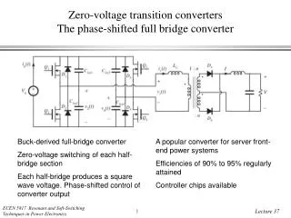
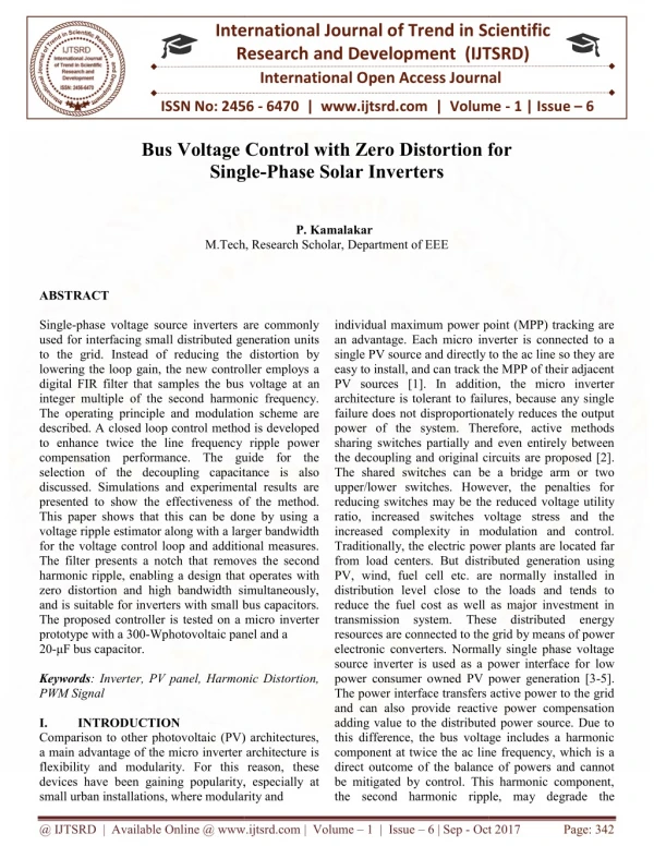
Single phase voltage source inverters are commonly used for interfacing small distributed generation units to the grid. Instead of reducing the distortion by lowering the loop gain, the new controller employs a digital FIR filter that samples the bus voltage at an integer multiple of the second harmonic frequency. The operating principle and modulation scheme are described. A closed loop control method is developed to enhance twice the line frequency ripple power compensation performance. The guide for the selection of the decoupling capacitance is also discussed. Simulations and experimental results are presented to show the effectiveness of the method. This paper shows that this can be done by using a voltage ripple estimator along with a larger bandwidth for the voltage control loop and additional measures. The filter presents a notch that removes the second harmonic ripple, enabling a design that operates with zero distortion and high bandwidth simultaneously, and is suitable for inverters with small bus capacitors. The proposed controller is tested on a micro inverter prototype with a 300 Wphotovoltaic panel and a 20 u00b5-F bus capacitor. P.Kamalakar "Bus Voltage Control with Zero Distortion for Single-Phase Solar Inverters" Published in International Journal of Trend in Scientific Research and Development (ijtsrd), ISSN: 2456-6470, Volume-1 | Issue-6 , October 2017, URL: https://www.ijtsrd.com/papers/ijtsrd2505.pdf Paper URL: http://www.ijtsrd.com/engineering/electrical-engineering/2505/bus-voltage-control-with-zero-distortion-for-single-phase-solar-inverters/pkamalakar<br>

E N D
International Research Research and Development (IJTSRD) International Open Access Journal Bus Voltage Control with Zero Distortion for Single-Phase Solar Inverters International Journal of Trend in Scientific Scientific (IJTSRD) International Open Access Journal ISSN No: 2456 ISSN No: 2456 - 6470 | www.ijtsrd.com | Volume 6470 | www.ijtsrd.com | Volume - 1 | Issue – 6 Bus Voltage Control with Zero Distortion for Single Bus Voltage Control with Zero Distortion for P. Kamalakar M.Tech, Research Scholar, M.Tech, Research Scholar, Department of EEE individual maximum power point (MPP) tracking are an advantage. Each micro inverter is connected to a single PV source and directly to the easy to install, and can track the MPP of PV sources [1]. In addition, the micro inverter architecture is tolerant to failures, because any single failure does not disproportionately reduces the output power of the system. Therefore, a sharing switches partially and even entirely between the decoupling and original circuits The shared switches can be a bridge arm or upper/lower switches. However, the penalties for reducing switches may be the reduced ratio, increased switches voltage stress and the increased complexity in modulation and control. Traditionally, the electric power from load centers. But distributed PV, wind, fuel cell etc. are norma distribution level close to the loads and tends to reduce the fuel cost as well as major investment in transmission system. These distributed energy resources are connected to the grid electronic converters. Normally sing source inverter is used as a power interface for power consumer owned PV power generation [3 The power interface transfers active power to the grid and can also provide reactive power compensation adding value to the distributed po this difference, the bus voltage includes a harmonic component at twice the ac line direct outcome of the balance of powers be mitigated by control. This harmonic component, the second harmonic ripple, ma the second harmonic ripple, may degrade the ABSTRACT Single-phase voltage source inverters are commonly used for interfacing small distributed generation units to the grid. Instead of reducing the distortion by lowering the loop gain, the new controller employs a digital FIR filter that samples the bus voltage at integer multiple of the second harmonic frequency. The operating principle and modulation scheme are described. A closed loop control method is developed to enhance twice the line frequency ripple compensation performance. The guide for the selection of the decoupling capacitance is also discussed. Simulations and experimental results are presented to show the effectiveness of the This paper shows that this can be done by using a voltage ripple estimator along with a larger bandwidth for the voltage control loop and additional measures. The filter presents a notch that removes the second harmonic ripple, enabling a design that operates zero distortion and high bandwidth simultaneously, and is suitable for inverters with small bus capacitors. The proposed controller is tested on a micro inverter prototype with a 300-Wphotovoltaic panel and a 20-μF bus capacitor. Keywords: Inverter, PV panel, Harmonic Distortion, PWM Signal I. INTRODUCTION Comparison to other photovoltaic (PV) architectures, a main advantage of the micro inverter architecture is flexibility and modularity. For this reason, these devices have been gaining popularity, especially at small urban installations, where modularity and installations, where modularity and phase voltage source inverters are commonly for interfacing small distributed generation units of reducing the distortion by power point (MPP) tracking are inverter is connected to a single PV source and directly to the ac line so they are easy to install, and can track the MPP of their adjacent PV sources [1]. In addition, the micro inverter architecture is tolerant to failures, because any single does not disproportionately reduces the output system. Therefore, active methods and even entirely between the decoupling and original circuits are proposed [2]. The shared switches can be a bridge arm or two upper/lower switches. However, the penalties for switches may be the reduced voltage utility switches voltage stress and the controller employs a digital FIR filter that samples the bus voltage at an integer multiple of the second harmonic frequency. principle and modulation scheme are method is developed to enhance twice the line frequency ripple power compensation performance. The guide for the decoupling capacitance is also discussed. Simulations and experimental results are e effectiveness of the method. This paper shows that this can be done by using a ripple estimator along with a larger bandwidth loop and additional measures. modulation and control. Traditionally, the electric power plants are located far from load centers. But distributed generation using PV, wind, fuel cell etc. are normally installed in distribution level close to the loads and tends to fuel cost as well as major investment in These distributed energy resources are connected to the grid by means of power electronic converters. Normally single phase voltage source inverter is used as a power interface for low power consumer owned PV power generation [3-5]. power interface transfers active power to the grid provide reactive power compensation distributed power source. Due to voltage includes a harmonic component at twice the ac line frequency, which is a direct outcome of the balance of powers and cannot be mitigated by control. This harmonic component, removes the second e, enabling a design that operates with zero distortion and high bandwidth simultaneously, suitable for inverters with small bus capacitors. controller is tested on a micro inverter Wphotovoltaic panel and a : Inverter, PV panel, Harmonic Distortion, Comparison to other photovoltaic (PV) architectures, main advantage of the micro inverter architecture is flexibility and modularity. For this reason, these been gaining popularity, especially at @ IJTSRD | Available Online @ www.ijtsrd.com @ IJTSRD | Available Online @ www.ijtsrd.com | Volume – 1 | Issue – 6 | Sep - Oct 2017 Oct 2017 Page: 342
International Journal of Trend in Scientific Research and Development (IJTSRD) ISSN: 2456-6470 efficiency and stability of the inverter if not handled appropriately by the inverter control circuitry [6]. Traditionally, the bus capacitor has been a high- capacitance low-voltage However, electrolytic capacitors are known to have limited lifetime and are not compatible with the 20 year or longer lifetime that is desired for modern solar power systems. To increase the system lifetime, a high-voltage film or similar capacitor for energy storage is preferred. Because of their increased cost, the size of these capacitors must be minimized [7]. Each micro inverter is connected to a single PV source and directly to the ac line so they are easy to install, and can track the MPP of their adjacent PV sources. In addition, the micro inverter architecture is tolerant to failures, because any single failure does not disproportionately reduces the output power of the system. The capacitor between these stages, the bus capacitor, is an internal energy storage device. The energy and consequently, the voltage on this capacitor are determined by the difference in power, the constant input power that charges the capacitor, and the pulsating output power that discharges it. Due to this difference, the bus voltage includes a harmonic component at twice the ac line frequency, which is a direct outcome of the balance of powers and cannot be mitigated by control [8,9]. This harmonic component, the second harmonic ripple, may degrade the efficiency and stability of the inverter if not handled appropriately by the inverter control circuitry. Traditionally, the bus capacitor has been a high- capacitance low-voltage However, electrolytic capacitors are known to have limited lifetime and are not compatible with the 20 year or longer lifetime that is desired for modern solar power systems [10]. To increase the system lifetime, a high voltage film or similar capacitor for energy storage is preferred. Because of their increased cost, the size of these capacitors must be minimized [11,12]. II. BACKGROUND AND MOTIVATION Integration of PV power generation systems in the grid plays an important role in securing the electric power supply in an environmentally-friendly manner. Grid-connected PV inverters are needed to extract the energy from the PV modules and feed it into the utility grid while ensuring the power quality follows certain grid interconnection standards such as IEEE- 1547. Under the micro FIT program, they will be paid a much higher price for the electricity that the projects produce comparing to the standard price people pay for their electricity. Particularly, for PV rooftop generation, the contract price paid is 80.2 cents/kWh, whereas the blended rate of electricity in Ontario is 7.74 cents/kWh in the summer period. Therefore, with the help of such stimulation programs, a growing market exists for residential PV inverters. Many companies such as National Semiconductor and Emphases are expanding their business in the area of residential PV inverters. A.Photovoltaic Photo voltaic (PV) is the name of a method of converting solar energy into direct current electricity using semiconducting materials that exhibit the photovoltaic effect, a phenomenon commonly studied in physics, photo chemistry and electro chemistry. It was billed as a solar battery and was mostly just a curiosity as it was too expensive to gain widespread use. In the1960s, the space industry began to make the first serious use of the technology to provide power aboard spacecraft. Through the space programs, the technology advanced, its reliability was established, and the cost began to decline. Grid connected PV systems are categorized based on the number of power stages. electrolytic capacitor. electrolytic capacitor. Fig.1 Centralized inverter configuration B.Two Stage Inverters In order to improve the energy harvesting capabilities and design flexibility, dedicated DC/DC converters, which perform MPPT for each PV string, can be connected in the middle between the PV modules and the DC/AC inverter. The system shown has its PCC at the AC terminal. This system type benefits from its modularity and the capability of plug and-play installation by users that possess limited knowledge of electrical systems. The output from the DC/DC converter in this configuration can be either a low ripple DC voltage, or a modulated current that follows a rectified sine wave. In the latter case, the DC/DC converter handles MPPT and output current regulation while the DC/AC inverter switches at the grid @ IJTSRD | Available Online @ www.ijtsrd.com | Volume – 1 | Issue – 6 | Sep - Oct 2017 Page: 343
International Journal of Trend in Scientific Research and Development (IJTSRD) ISSN: 2456-6470 frequency to unfold the rectified sine wave. Reference[10] is an example of the unfolding configuration. Fig.2 PV Panel The diagram above illustrates the operation of a basic photovoltaic cell, also called a solar cell. Solar cells are made of the same kinds of semiconductor materials, such as silicon, used in the microelectronics industry. For solar cells, a thin semiconductor wafer is specially treated to form an electric field, positive on one side and negative on the other. When light energy strikes the solar cell, electrons are knocked loose from the atoms in the semiconductor material. If electrical conductors are attached to the positive and negative sides, forming an electrical circuit, the electrons can be captured in the form of an electric current -- that is, electricity. This electricity can then be used to power a load, such as a light or a tool. Fig.3 PV Array Module Multiple modules can be wired together to form an array. In general, the larger the area of a module or array, the more electricity that will be produced. Photovoltaic modules and arrays produce direct- current (dc) electricity. They can be connected in both series and parallel electrical arrangements to produce any required voltage and current combination. III. PROPOSED SYSTEM This paper explains the tradeoff between bandwidth and harmonic distortion in the bus voltage loop, and provides anew control method for regulating the bus voltage, a method that is simple, low cost, and does not require additional hardware. The proposed controller uses a digital finite impulse response (FIR) filter that samples the bus voltage at a slow sampling rate that is an integer multiple of the ac line second harmonic frequency. This digital filter achieves what a simple analog feedback cannot; it extracts the low- frequency components of the bus voltage signal, measuring the average bus voltage, while effectively filtering the noise of the second harmonic ripple. A.Reducing the Size of the DC-link Capacitor Therefore, the DC-link contains power pulsation with twice the grid frequency. Often, large electrolytic capacitors are connected to the DC-link to absorb this power pulsation so that the DC-link voltage ripple can be kept small. However, most PV module manufactures offer 25 year warranties on 80% of the @ IJTSRD | Available Online @ www.ijtsrd.com | Volume – 1 | Issue – 6 | Sep - Oct 2017 Page: 344
International Journal of Trend in Scientific Research and Development (IJTSRD) ISSN: 2456-6470 initial efficiency and five years warranty on materials and workmanship [8]. capacitors with large capacitance cannot be used in PV applications because of their short lifetime. Many techniques were proposed to reduce the size of the DC-link capacitor while maintaining a good inverter power quality so that a more reliable film type capacitor can the switches used in the auxiliary circuit must have rating comparable to the main power stage switches. Therefore, although such methods can solve the problem of double-line frequency ripple, they are not a viable solution considering the extra cost and energy loss associated with the introduction of the auxiliary circuit. REFERENCES 1)G. communication signals,” Electricity, Ecole Poly technique Federalae de Lausanne, Switzerland, 2004. 2)J. d. R. Milan, Brain Computer Interfaces, Handbook of Brain Theoryand Neural Networks, 2nd ed., Cambridge, MA, The MIT Press, 2002. 3)J. R. Wolpaw, D. J. McFarland, T. M. Vaughan, “Brain ComputerInterface Research at the Wads worth Center,” IEEE Transactions on Neural Systems, Eng, vol. 8, 2000. 4)N. Birbaumer, “A spelling device for the paralyzed,” Nature, vol. 398,1999. 5)J. Kalcher, “Graz brain-computer interface II,” Med. & Biol. Eng. &Comput., vol. 34, 1996. 6)B. Obermaier, C. Neuper, C. Guger, G. Pfurtscheller, “InformationTransfer Rate in a Five-Classes Brain Computer Interface,” IEEE Transactions on Neural Rehabilitation Engineering, vol. 9,no. 3, 2001. 7)J. R. Wolpaw, D. J. McFarland, “Multichannel EEG based braincomputer communication,” Electro enceph. Neuro physiol. vol. 90, 1994. 8)C. W. Anderson, “Effects of variations in neural networks topology andoutput averaging on the discriminations of spontaneousEEG,” Journal of Intelligent System, vol. 7, pp. 165–190, 1997. 9)J. d. R. Milan, Brain Computer Interfaces, Handbook of Brain Theoryand Neural Networks, Second editions, Cambridge, MA, The MIT Press,2002. 10)J. D. Bayliss, “Use of the Evoked Potential P3 Components for Controlin a Virtual Apartment,” IEEE Transactions Engineering,vol. 11, no. 2, 2003. 11)B. Obermaier, G. Müller, G. Pfurtscheller, “‘Virtual Keyboard’controlled by spontaneous EEG activity,” Proc. of the Int. Conference onArtificial Neural Springer-Verlag, 2001. 12)J. del R. Millán and J. Mourino, “Asynchronous BCI and local neuralclassifiers: an overview of the adaptive brain interface project,” IEEE 13)Transactions on Neural Rehabilitation Engineering, vol. 11,no. 2, pp. 159– 161, 2003 Therefore, electrolytic N. Garcia, brain-computer scalprecorded thesis, Department “Direct through EEG Doctor’s of Systems and Fig.5 Circuit Diagram IV. In PV micro inverters, a major challenge that one encounters when designing the bus voltage loop is the trades off between distortion and bandwidth, and the bus capacitor size, a tradeoff that is difficult and even impossible to solve when the bus capacitor is small and the second harmonic ripple is high. This paper analyzes this tradeoff, providing expressions for the harmonic distortion, and evaluating the loop dynamics. A conclusion of this analysis is that both the distortion and the bandwidth are affected by one main parameter, the loop gain. To eliminate this tradeoff, this paper proposes a digital controller that operates with low distortion and high bandwidth simultaneously. Instead of reducing the distortion for mitigating the ripple, the digital controller uses a FIR filter that samples the bus voltage at a rate that is an integer multiple of the second harmonic frequency, and presents a notch that removes the second harmonic ripple. This enables a simple and low cost design, a design that has high band width, causes negligible distortion in the ac line current, can be implemented with an inexpensive microcontroller, and operates well with a small bus capacitor. CONCLUSION mental task from Rehabilitation Networks, Heidelberg: Systems and @ IJTSRD | Available Online @ www.ijtsrd.com | Volume – 1 | Issue – 6 | Sep - Oct 2017 Page: 345