Download
1 / 12
120 likes | 138 Views
This document discusses the issue of scurve distortion and VDC Vled control voltage in AERO (AtlasEndcapReadOut) modules. It explores the use of opto chips for readout, the impact of VLED on noise occupancy, and possible solutions to reduce the discontinuity. The document also suggests operating with reduced VLED and switching to a lower trigger frequency for improved performance.

E N D
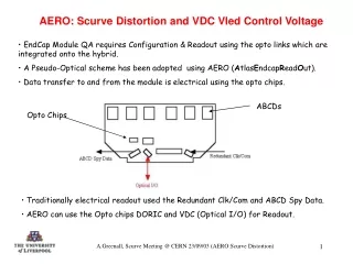
AERO: Scurve Distortion and VDC Vled Control Voltage • EndCap Module QA requires Configuration & Readout using the opto links which are integrated onto the hybrid. • A Pseudo-Optical scheme has been adopted using AERO (AtlasEndcapReadOut). • Data transfer to and from the module is electrical using the opto chips. ABCDs Opto Chips • Traditionally electrical readout used the Redundant Clk/Com and ABCD Spy Data. • AERO can use the Opto chips DORIC and VDC (Optical I/O) for Readout. A.Greenall, Scurve Meeting @ CERN 23/09/03 (AERO:Scurve Distortion)
AERO: Scurve Distortion and VDC Vled Control Voltage • But when using AERO a discontinuity can be seen on the Noise Occupancy Scan, all other electrical tests are ok: Corresponds to nearly all comparators switching off Discontinuity VLED = 5.5V Scurves switch off quickly at ~ 0.24fC • Discontinuity tends only to be apparent on those chips at the edge of the hybrid – impedance changes on hybrid(?), chips at the edge are farthest away from the power connector. A.Greenall, Scurve Meeting @ CERN 23/09/03 (AERO:Scurve Distortion)
AERO: Scurve Distortion and VDC Vled Control Voltage • AERO can do an emulation of Melbourne Support Card (where COM1/CLK1 are used and data is readout directly from the ABCDs – no opto chips are used). • Discontinuity can still be seen on the Noise Occupancy Scan. Discontinuity Melbourne Support Card Emulation Noise Occupancy Scan • Problem appears to be peculiar to AERO whichever Readout mode is used….Melbourne Support Cards never show this problem. A.Greenall, Scurve Meeting @ CERN 23/09/03 (AERO:Scurve Distortion)
AERO: Scurve Distortion and VDC Vled Control Voltage • Why the discontinuity in Melbourne emulation? • Previous plot was obtained with VLED set to 5.5V. Thus the VDC chip was still transmitting data – AERO ignores this data and uses the ABCD Spydata instead. • Repeat Noise Occupancy Scan BUT this time set VLED to 0V – this forces the VDC not to transmit data. Discontinuity has now reduced • How or why should the VDC have such an affect? A.Greenall, Scurve Meeting @ CERN 23/09/03 (AERO:Scurve Distortion)
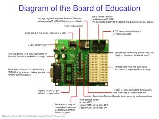
AERO: Scurve Distortion and VDC Vled Control Voltage VDD brought off Hybrid to AERO Wiggly Kapton and Ethernet Cable to AERO Schematic of VDC Electrical Readout (using AERO) • VLED sets the control current for the output drivers of the VDC, increasing this control current will increase the voltage swing of the output signal of the VDC A.Greenall, Scurve Meeting @ CERN 23/09/03 (AERO:Scurve Distortion)
AERO: Scurve Distortion and VDC Vled Control Voltage • Schematic shows that the VDC data transmission is single-ended. • Whereas for Redundant Readout data transmission is differential. • For AERO, the VDC output is sensed remotely from the hybrid using long electrical lines (which can introduce an impedance). • Thus one could infer that either: • The VDC output is somehow being coupled (capacitively?) back into the module. • or • Changes in the digital power supply VDD are being coupled back into the front-end of the ABCD. The use of ‘long’ cables, between AERO and the Patch Card can introduce an impedance so as the VDC switches this could cause the VDD on the hybrid to change. A.Greenall, Scurve Meeting @ CERN 23/09/03 (AERO:Scurve Distortion)
AERO: Scurve Distortion and VDC Vled Control Voltage • So 2 possible solutions exist: • Electrically screen the Wiggly Kaptons so as to stop the VDC output being coupled back into the module….assuming it is being capacitively coupled. • Reduce the magnitude of the VDC output signal i.e. reduce VLED. By doing this will reduce any changes seen on the VDD power supply. • Option 1 is not realistic thus Option 2 maybe the only solution. • So Noise Occupancy Scans were repeated for various values of VLED (6V to 2V). A.Greenall, Scurve Meeting @ CERN 23/09/03 (AERO:Scurve Distortion)
AERO: Scurve Distortion and VDC Vled Control Voltage Noise Occupancy Plots for reducing VLED: VLED = 6.0V VLED = 5.0V VLED = 4.0V Clearly as VLED reduces so does the discontinuity VLED = 3.0V VLED = 2.0V A.Greenall, Scurve Meeting @ CERN 23/09/03 (AERO:Scurve Distortion)
AERO: Scurve Distortion and VDC Vled Control Voltage Therefore operating with reduced VLED it might be possible to obtain a Noise Occupancy with little or no distortion of the Scurves. The following plot(s) were obtained for VLED set to 2.8V using 5m cables linking AERO to the Module: Scurves now show reduced discontinuity A.Greenall, Scurve Meeting @ CERN 23/09/03 (AERO:Scurve Distortion)
AERO: Scurve Distortion and VDC Vled Control Voltage • Low Trigger Frequency Operation • All tests so far have used CLOAC for Module Triggering (for Noise Occupancy): • Uses a Variable Trigger Rate which peaks at 100KHz • Switch to non-CLOAC system (fixed Trigger frequency of ~ 35KHz), operating at a lower frequency should reduce the presence of switching transients on the VDD power supply – assuming that this is the problem one should be able to operate with a larger value of VLED with a reduced discontinuity on the Noise Occupancy Scan: VLED = 5.5V VLED = 2.8V • Little discernable difference between the 2 plots – Scurves on next slide A.Greenall, Scurve Meeting @ CERN 23/09/03 (AERO:Scurve Distortion)
AERO: Scurve Distortion and VDC Vled Control Voltage Pseudo-Optical Readout with No-CLOAC for VLED = 5.5V and 2.8V VLED = 5.5V Switching off fast at beginning? Scurves now show no discontinuity VLED = 2.8V A.Greenall, Scurve Meeting @ CERN 23/09/03 (AERO:Scurve Distortion)
AERO: Scurve Distortion and VDC Vled Control Voltage • Conclusions • For Noise Occupancy there appears to be a correlation between the magnitude of the VDC output switching signal and distortion seen on the Scurves – by reducing VLED one can reduce this affect….but there is a limit to which VLED can be set (Nominal Vlaue is 4.1V). • Further improvement can be obtained by operating at a reduced Trigger rate – but this will result in a ‘compromised’ Noise Occupancy Scan (Module is not being tested at the SCT nominal trigger frequency of 100KHz). • Should we worry……maybe not(?) • If the problem is due to the VDC transmitting data electrically down ‘long’ cables then with true optical readout this problem will not exist – VDC track lengths are of the order of mm NOT metres (when compared to AERO). • 2 Pre-qualification modules tested with AERO – which show this problem – will/should be tested on Test Sector to verify that this is the problem. A.Greenall, Scurve Meeting @ CERN 23/09/03 (AERO:Scurve Distortion)