Download
1 / 56
570 likes | 696 Views
This PhD thesis proposal discusses the methodologies for generating test vectors at the register-transfer level (RTL) using spectral methods. It addresses the challenges associated with test generation, emphasizing the need for high-quality test vectors, fault coverage, and reduced complexity. The proposal includes a review of spectral analysis, the advantages and disadvantages of various test generation methods, and recent advances in RTL design for testability (DFT). The document outlines the goals for generating functional test vectors and seeks to address gaps between RTL and gate-level coverage.

E N D
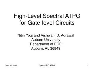
Gate-Level Test Generation Using Spectral Methods at Register-Transfer Level Nitin Yogi – PhD Thesis Proposal May 04, 2007, 3 p.m. Committee Members: Prof. Victor P. Nelson Prof. Adit D. Singh Prof. Charles E. Stroud Advisor: Prof. Vishwani D. Agrawal General Oral Examination
Outline • Introduction • Background • Spectral Register Transfer Level (RTL) test generation • RTL Design for Testability (DFT) • Results • Future Work • Conclusion General Oral Examination
1 - Introduction • Test generation challenges • Test generation methods • Problem definition General Oral Examination
1.1 – Test Generation Challenges • Two main challenges • Reducing test generation complexity • Majority circuits sequential in nature • Rise in design complexity • Good quality test vectors • High fault coverage • Low yield loss General Oral Examination
1.2 – Test Generation Methods • Scan-Based Test Generation • Sequential Test Generation • Register-Transfer Level (RTL) Test Generation • Pseudo Functional Test Generation General Oral Examination
1.2.1 – Scan-Based Test Generation CombinationalLogic Circuit Outputs Circuit Inputs Scan Output Functional FF FF Scan FF FF Scan Scan chain Scan Input General Oral Examination
1.2.1 – Scan-Based Test Generation • Advantages: • Reduced test generation complexity • Combinational test generation • High fault coverage • Disadvantages: • Area overhead (~ 5 – 10%)Timing overhead (~ 5 – 10%) • Non-functional tests • Long test times • Issues from high test power • Voltage droop • Ground bounce • Issues with at-speed scan tests • False and multi-cycle paths General Oral Examination
1.2.2 – Sequential Test Generation • Non-scan test generation • Advantages • Functional vectors • Short test times • No test power issues • Ability to generate at-speed tests • Disadvantages • High test generation complexity General Oral Examination
1.2.3 – RTL Test Generation • Earlier Work [Jha et.al.,Hayes et. al.,Goloubeva et. al.] • Advantages: • Low test generation complexity • Less amount of information to process • Early detection of testability issues • Synthesis independent • Disadvantages: • Main issues • Closing gap between RTL and gate-level coverage • High engineering effort • No established method General Oral Examination
1.2.4 – Pseudo Functional Test Generation • Weighted random vectors (Brglez et. al.) • Test vectors generated with certain probabilities of being logic ‘0’ or ‘1’ • PROPTEST (Guo et. al.) • Property based test generation • Probabilities, holding, perturbation • Spectral methods (Giani et. al., Khan et. al.) • Test generation using spectral properties • Retrieve spectral properties • Generate new vectors with those properties General Oral Examination
1.3 – Problem Definition • Summary of goals • Generate functional test vectors • Sequential test generation • Low test generation complexity • RTL test generation • Convenient test generation method • Spectral methods • Hence the problem is … • To generate function vectors using sequential test generation by using spectral methods at RTL General Oral Examination
Outline • Introduction • Background • Spectral Register Transfer Level (RTL) test generation • RTL Design for Testability (DFT) • Results • Future Work • Conclusion General Oral Examination
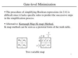
2 – Background • Spectral analysis for test generation • Walsh functions and Hadamard matrix General Oral Examination
2.1 – Spectral Analysis for Test Generation • Spectral analysis: Interpret information in frequency domain • Test generation • Good quality test vectors exhibit certain spectral characteristics • Goals: • Determine relevant spectral characteristics • Generate vectors with those characteristics General Oral Examination
2.2 Walsh functions and Hadamard matrix • Walsh functions: a complete orthogonal set of basis functions that can represent any arbitrary bit-stream. • Walsh functions form the rows of a Hadamard matrix. w0 w1 w2 H8 = 1 1 1 1 1 1 1 1 1 -1 1 -1 1 -1 1 -1 1 1 -1 -1 1 1 -1 -1 1 -1 -1 1 1 -1 -1 1 1 1 1 1 -1 -1 -1 -1 1 -1 1 -1 -1 1 -1 1 1 1 -1 -1 -1 -1 1 1 1 -1 -1 1 -1 1 1 -1 w3 w4 Walsh functions (order 8) w5 w6 w7 time Example of Hadamard matrix of order 8 General Oral Examination Move to next section
Outline • Introduction • Background • Spectral Register Transfer Level (RTL) test generation • RTL Design for Testability (DFT) • Results • Future Work • Conclusion General Oral Examination
3 – Spectral RTL Test Generation • Spectral characterization • Spectral vector generation • Test set minimization General Oral Examination
3.1 – Spectral Characterization • Purpose – Determine relevant spectral characteristics • Premise – Vectors detecting RTL faults exhibit important spectral characteristics • Steps • RTL fault modeling and test generation • Spectral analysis General Oral Examination
3.1.1 – RTL Fault Modeling CombinationalLogic Inputs Outputs RTL fault sites FF FF A circuit is an interconnect of several RTL modules. General Oral Examination
3.1.2 – Spectral Analysis Input 1 Input 2 . . . Vector 1 Vector 2 . . . Bit-stream 0 to -1 Bit-stream of Input 2 General Oral Examination
3.1.2 – Spectral Analysis (cont.) Bit stream to analyze Correlating with Walsh functions by multiplying with Hadamard matrix. Bit stream Spectral coeffs. Hadamard Matrix H(3) Essential component (others regarded noise) General Oral Examination
Power Spectrum: “Ready” Signal PARWAN Processor Circuit Examples of Essential components Examples of Noise components Normalized Power Noise level(1/128) Spectral Coefficients General Oral Examination
Power Spectrum: A Random Signal Normalized Power Noise level(1/128) Spectral Coefficients General Oral Examination
3.2 – Spectral Vector Generation Perturbation Spectral components Generation of new bit-stream by multiplying with Hadamard matrix Essential component retained noise components randomly perturbed Sign function New bit stream -1 to 0 Bits changed General Oral Examination
3.3 – Test Set Minimization • Fault simulation of new sequences • Set of perturbation vector sequences {V1, V2, .. , VM} are generated. • Vector sequences are fault simulated and faults detected by each is obtained. • Minimization problem • Find minimum set of vector sequences covering all the detected faults. • Minimize Count{V1, … ,VM} to obtain compressed seq. {V1,… ,VC} Fault Coverage{V1, … ,VC} = Fault Coverage{V1, … ,VM} • Compaction problem formulated as an Integer Linear Program (ILP) *. * P. Drineas and Y. Makris, “Independent Test Sequence Compaction through Integer Programming," Proc. ICCD’03, pp. 380-386. General Oral Examination
3.3.1 – ILP test minimization • Set of integer [0,1]variables { tj } – one for each vector sequence • tj = 0: drop sequence ; tj = 1: select sequence • Set of constraints{ ck }–one for each fault • Example: for kth fault detected by vector sequences u, v and wck : tu + tv + tw≥ 1 • Objective function • Minimize∑ tj ; j = 1 to N General Oral Examination
3.3.2 – Hybrid LP – ILP • Approximate solution to ILP (Relaxed LP, Rounding)* • Algorithm: 1. All variables redefined as real [0,1] real variables(LP model) 2. Loop : 1. Solve LP 2. Round variables to add constraints 1. Round to 0 if ( 0.0 <variables≤ 0.1) 2. Round to 1 if ( 0.9 ≤variables< 1.0) 3. Exit loop if no variables are rounded 3. Reconvert variables to [0,1] integers and solve ILP * Kantipudi, K.R.; Agrawal, V.D, “A Reduced Complexity Algorithm for Minimizing N-Detect Tests”, 20th International Conference on VLSI Design, 2007 General Oral Examination
Outline • Introduction • Background • Spectral Register Transfer Level (RTL) test generation • RTL Design for Testability (DFT) • Results • Future Work • Conclusion General Oral Examination
4 – RTL Design for Testability • Goals of DFT: • Improve fault coverage • XOR tree as DFT • Low area overhead • Low performance penalty • Does not change state machine • Hard-to-detect RTL faults used for observation test points XOR tree To test output Hard-to-detect RTL faults General Oral Examination
Outline • Introduction • Background • Spectral Register Transfer Level (RTL) test generation • RTL Design for Testability (DFT) • Results • Future Work • Conclusion General Oral Examination
5 – Results • Experimental Circuits • Spectral RTL test generation • Stuck-at faults • Transition delay faults General Oral Examination
5.1 – Experimental Circuits • Experimental Circuits • 4 ITC’99 high level RTL circuits • 4 ISCAS’89 circuits. • PARWAN processor* • Commercial sequential ATPG tool Mentor Graphics FlexTest for test generation and fault simulation. • Results obtained on Sun Ultra 5 machines with 256MB RAM. * Z. Navabi, VHDL: Analysis and Modeling of Digital Systems, McGraw-Hill, 1993. General Oral Examination
5.2.1 – ATPG for stuck-at faults General Oral Examination
PARWAN* Processor * Z. Navabi, VHDL: Analysis and Modeling of Digital Systems, McGraw-Hill, 1993. General Oral Examination
Results – Test Generation $Sun Ultra 5, 256MB RAM * Reset input added. General Oral Examination
Results – Test Generation and RTL DFT *Sun Ultra 5, 256MB RAM General Oral Examination
5.2.2 – ATPG for transition faults General Oral Examination
Results – Test Generation s-a-f: stuck-at faults t-f : transition faults * Sun Ultra 5, 256MB RAM General Oral Examination
Outline • Introduction • Background • Spectral Register Transfer Level (RTL) test generation • RTL Design for Testability (DFT) • Results • Future Work • Conclusion General Oral Examination
6 – Future Work • Fourier Analysis of Digital Waveforms • Spectral BIST General Oral Examination
6.1 – Fourier Analysis of Digital Waveforms • Fourier Transform – converts signals to frequency domain • Digital bit-streams can be perceived as sampled analog signals • Important properties (not exhibited by Walsh functions) • Frequency decomposition using Fourier transform is invariant to phase or circular time-shift • Multiplication = Convolution (frequency domain) (time domain) • Other advantages of Fourier Transform over Walsh • Established methods for noise analysis • Methods to find Power Spectral Density (PSD) General Oral Examination
6.2.1 – Built-In Self Test • Built-In Self Test (BIST) • Hardware inserted to: • Generate test vectors • Capture responses of CUT • Flag CUT good or bad System Inputs Test generator Wrapper Circuit Under Test (CUT) CUT status Response Analyzer System Outputs General Oral Examination
Motivation for Spectral BIST • BIST • Advantages: • No need of expensive Automatic Test Equipment (ATE) • Testing during operation and maintenance • Supports system level test • Supports at-speed testing • And many more … • Disadvantages: • Low coverage test vectors • Area / timing overhead • Problem is… • To design a test pattern generator with spectral information that generates high coverage test vectors General Oral Examination
Fourier Transform of Test Bit-Stream Prominent features General Oral Examination
6.2.2 – Spectral BIST Test generator Spectral Test Generator System Inputs Spectral Filter Wrapper Circuit Under Test (CUT) CUT status Response Analyzer System Outputs General Oral Examination
Digital Filter Design • If y : output of filter x : input of filter n : time period p : order of filter • Infinite Impulse Response (IIR) • y(n) = f (y(n-1), ….. y(n-p), x(n), x(n-1), … x(n-p)) • Finite Impulse Response (FIR) • y(n) = f (x(n), x(n-1), … x(n-p)) • IIR would require more hardware than FIR General Oral Examination
Spectral Test Generator LFSR Spectral Test Generator Test generator Spectral Filter FIR filter General Oral Examination
FIR Filter Design FIR filter General Oral Examination
FIR filtering Random bit-stream after filtering Random bit-stream Filter General Oral Examination
How good is the filtered bit-stream ? Original test bit-stream Random bit-stream after filtering General Oral Examination