Download

1 / 32
320 likes | 527 Views
Towards the integration of the Micro Vertex Detector in the PANDA experiment. Daniela Calvo INFN – Sezione di Torino on behalf of the PANDA MVD group PANDA Collaboration. TIPP’14 - International Conference on Technology and Instrumentation in Particle Physics

E N D
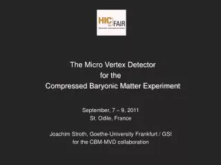
Towards the integration of the Micro Vertex Detector in the PANDA experiment Daniela Calvo INFN – Sezione di Torino on behalf of the PANDA MVD group PANDA Collaboration TIPP’14 - International Conference on Technology and Instrumentation in Particle Physics 2-6 June 2014, Amsterdam, The Netherlands
Overview • Introduction • Pixel and strip modules • Readout architecture • Service integration • Detector prototypes • Conclusions
TARGET SPECTROMETER FORWARD SPECTROMETER Solenoid Dipole Target Muon ID Drift Chambers Muon Range System Central Tracker Electromag. Calorimeters DIRC Vertex RICH The PANDA experiment p beam PANDA is a fixed target experiment with frozen hydrogen pellet and heavier nuclear targets (N, Ne, Ar…) Hadron spectroscopy In-medium effects Hypernuclear physics Charmed hadrons 4 p acceptance High spatial and momentum resolution No hardware trigger
The Micro Vertex Detector Tasks • It must combine good space resolution with accurate time-tagging • Main functions • Primary vertex reconstruction • Identification of the secondary vertices (c of some hundreds of m) • Improvement in momentum resolution • Support PID of low momentum particles by energy loss measurement
The Micro Vertex Detector • Good spatial resolution (some tens of mm in rf, better than 100 mm along z) • Time resolution < 10 ns • Continuous readout at 2 x 10⁷ interactions /s (clock @160 MHz) • Limited material budget X/Xo ≤ 1 % / layer • Radiation tolerance ˂ 1014n 1 MeV eq cm-2 • Provide at least four hits per track • Room temperature operation • Routing and services only in the backward region 4 barrels • Two inner layers: silicon hybrid pixel • Two outer layers: double-sided silicon strips 6 forward disks • Four disks: hybrid pixel detectors • Two last disks: mixed pixel and strips • 10.3 M (pixel channels) – active area: 0.106 m2 • 162 k (strip channels) – active area: 0.494 m2
Hybrid epitaxial pixels 810 readout chips / 176 sensors Standard hybrid technology • Epitaxial Silicon material • Pixel cell size: 100mm x 100mm x 100mm • repi ~ k∙cm • rCz ~ 20-50 m∙cm • ASIC in 130 nm CMOS tecnology • Triggerless • dE/dx using Time over Threshold technique • Layout based on a basic unit corresponding to a readout chip size • Modules are built by tiling from two to six units Wafer from ITME, pixel sensor from FBK
Pixel modules Pixel disk Pixel stave Total power 94 W Cooling pipe diameter 2 mm (Ni-Co alloy) 4 mm carbon foam Cooling flow 0,3 l/m Inlet temperature: 18.5 °C Th. conductivity = 50 W/m∙K
Double-sided silicon strips • Rectangular (512 x 896 strips) and squared (512 x 512 strips) sensors; • stereo angle: 90°, pitch: 65 mm • Trapezoidal (768 x 768 strips) sensors; stereo angle: 15°, pitch: 45 mm • 285 mm thickness (FZ silicon wafer) • Readout every second strip 3112 readout chips / 296 sensors Radiation damage test using 14 MeV proton beam @ Bonn CiS Erfurt
Strip staves Sandwich structure of carbon fiber (200 mm) and Rohacell (2 mm) Up to 18 W dissipated on one stave Embedded cooling pipe in Ni-Co alloy (2 mm diameter, 80 mm wall thickness) POCO HTC around the cooling pipe Characterization of the PANDA MVD Trapezoidal Silicon Strip Sensor and their First Operation in a Proton Beam Poster presented by D. Deermann
The Micro Vertex Detector Two halves arranged around the beam-target pipes suspended to the central tracker support pp → D± → k-p+p+k +p- p- Reconstructed D± mass Reconstructed D± decay length
Pixel detector architecture HV Power supply LV Power supply Pixel module Power lines Epitaxial silicon sensor DC-DC converter Hybrid e-links ToPix GBT Optical fibres SODA Computer node Optical fibres MVD Multiplexer Board Optical fibre
ToPix • Pixel matrix: 110 x 116 • Size (to be optimized): • 11.2 mm x 14.8 mm • dE/dx measurement: ToT, • 12 bits dynamic range • Maximum input charge: 50 fC • Detector type: n and p • Noise floor: < 200 electrons • Input clock frequency: 160 MHz • Time resolution: ~ 6 ns • Power consumption: ≤ 0.8 W/cm2 • Maximum event rate: 6.1 x 10⁶ • Total ionizing dose: < 100 kGy • Data rate per chip: • up to ~ 450 Mb/s • Output bandwidth: 2 x 320 Mb/s • Supply voltage: 1.2 V • Columns divided in 8 regions with 7 double columns each • FIFO in the end of column and region control
ToPix_v4 • ASIC size: 3 mm x 6 mm • 130 nm CMOS technology • Pixel matrix: 640 cells, 2x2x128 and 2x2x32 columns • Input clock frequency: 160 MHz • Compatible with the sensor of previous version (ToPix_v3) • Hamming encoding and TMR pixel logic protection • Leading and trailing edge registers withDICE -protected latches • SEU protected EoC • Serial data output (SDR and DDR) • GBT compatible SLVS I/O Measured perfomance @ 160 MHz clock 640 pixel DACs completely linear Easy calibration
Hybrid for the pixel module direct • Hybrid structure for 6 readout chips • Size: 67.9 mm x 11.9 mm • 15 mm Al thickness • 75 mm kapton thickness • 60 mm track width, 60 mm spacing • For each chip: • 3 differential pairs in daisy chain • 4 direct differential pairs • 27 differential pairs in total • ~ 100 ohm differential impedance • 12 smd capacitors direct long short UI Total jitter vs data rate Link diretto LVDS Link diretto SLVS Daisy chain lunga Daisy chain corta
straight coverless Total Jitter Signal transmission 1 m and 1.5 m long aluminum strip prototypes 18 differential pairs Technology based on laminated aluminum on kapton, reliable for bonding, produced @ CERN according to our design SLVS signals c u
Hybrid and cable hybrid PRBS from pulse generator 1.5 m long cable To oscilloscope SLVS signals
Strip detector architecture Double-sided silicon strip detector HV Power supply LV Power supply PASTA PASTA Power lines PASTA PASTA MDC MDC MDC MDC PASTA PASTA DC-DC converter e-links Hybrid flex adapter GBT Optical fibres SODA Computer node Optical fibres MVD Multiplexer Board Optical fibre
PASTA concept • 64 channel, 4.2 x 5 mm2 , self triggered chip • 110 nm CMOS technology • Input capacitance: < 50fF • Dynamic range: < 50fC • Power consumption: < 4 mW/ch • Channel pitch: 60 mm • Radiation protection: 100 KGy • Dynamic range: 8 bit • Amplification and discrimination • Time interpolation, Wilkinson ADC • Control charging and initiate storing • Handling configuration and channel data
Full hybrid PCB Folding of PCB around the stave to connect n-side and p-side r/o Reduced scale prototype
MVD services integration MVD DC-DC s GBTs 2840 mm In & Out fittings from front side • DC-DC circuit system composed of 3 sets of twin layers of boards, arranged around the beam pipe • 2112 DC-DC circuits (CERN) • 24 twin cooling bars equipped with 88 circuits each • 168 GBT circuits (CERN) • 12 cooling bars equipped with 14 circuits each • Thermal simulations in progress 360 Cooling tube embedded in an aluminum bar
Integration in PANDA MVD MVD Services Beam line pump 2840 Backward Calorimeter
Detector prototypes • Flex-PCB and 3.5 cm x 3.5 cm PANDA fullsize strip sensor (+APV25 chips) • Test @ COSY in 2014 • ToPix_3 prototype and the custom epitaxial silicon (ITME) sensor (FBK), 640 pixels arranged in long and short columns • Cz thinning + Bump bonding @ IZM (Berlin) using Sn-Pb bumps. • Yield of the tested assemblies : • ~ 99.5 % • The thin Cz layer is the ohmic contact for the sensor biasing. Single chip pixel assembly
Detector prototypes BEAM
Conclusions Challenging integration of the MVD in PANDA. The work is in progress on the service side and for both pixel and strip readout the custom developments are ongoing. The prototype results support our studyand design.
MDC - Module Data Concentrator • Time ordered hit packets (Hit Ring-Buffer) • Cluster-centroids and –sums after the 1d-clustering (Cluster Correlation Processor) • 2d-hit points after the CCP • Buffering by FIFOs
MVD services integration Cooling tube embedded into a aluminum bar In & Out fittings from front side • GBT circuits support structure is composed by two halves around the beam pipe • 168 GBT circuits (CERN) • 12 cooling bars equipped with 14 circuits each • Thermal simulations ongoing • Water as cooling fluid at 18 °C inlet 680