Download

1 / 41
410 likes | 957 Views
The Silicon Vertex Detector of the Belle II Experiment . Thomas Bergauer ( HEPHY Vienna). IEEE NSS 2011. Valencia. Belle and Belle II SVD Double Sided Sensors Readout System Chip-on-Sensor-Concept Summary. Belle. KEKB. Linac. KEKB and Belle @ KEK (1999-2010).

E N D
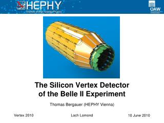
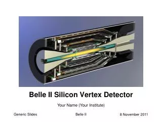
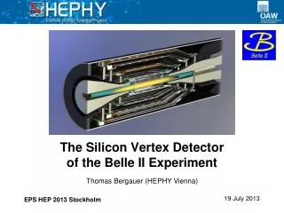
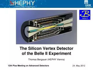
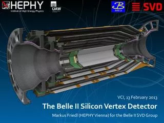
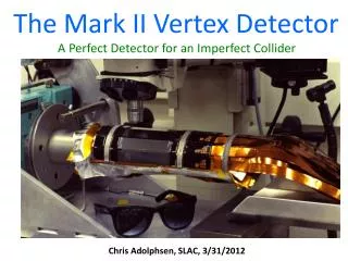
The Silicon Vertex Detector of the Belle II Experiment Thomas Bergauer (HEPHY Vienna) IEEE NSS 2011 Valencia
Belle and Belle II SVD Double Sided SensorsReadout SystemChip-on-Sensor-ConceptSummary T. Bergauer (HEPHY Vienna)
Belle KEKB Linac KEKB and Belle @ KEK (1999-2010) • Asymmetric machine:8 GeVe- on 3.5 GeVe+ Belle KEKB ~1 km in diameter Linac • Center of mass energy: Y(4S) (10.58 GeV) • High intensity beams (1.6 A & 1.3 A) • Integrated luminosity of 1 ab-1recorded in total • Belle mentioned explicitly in Physics Nobel Prize announcement to Kobayashi and Maskawa About 60km northeast of Tokyo T. Bergauer (HEPHY Vienna)
SuperKEKBand Belle II (2010–2014) • Aim: super-high luminosity ~81035 cm-2s-1 11010 BB / year • Refurbishment of accelerator and detector required • Schedule: • LoI published in 2004 • TDR was written in 2010 • Construction 2010-2014 • Commissioning 2014-2015 • Operation 2015 onwards http://belle2.kek.jp T. Bergauer (HEPHY Vienna)
Belle Silicon Vertex Detector (SVD) • Present SVD limitations are • occupancy (currently ~10% in innermost layer)need faster shaping • dead time (currently ~3%)need faster readout and pipeline • Belle II needs detector with • high background tolerance • pipelined readout • robusttracking • low material budget in active volume Current SVD is not suitable for Belle II T. Bergauer (HEPHY Vienna)
Previous SVD Layout (until 2010) • 4 straight layers of 4" double-sided silicon detectors (DSSDs) • Outer radius ofr~8.8 cm • Up to three 4” sensors are daisy- chained and read out by one hybridlocated outside of acceptance region T. Bergauer (HEPHY Vienna)
New Layout for Belle II SVD (2014-) • New double-layer pixel detector using DEPFET technology • Strip layers extend to r~14 cm • 6” sensors • Every sensor is read out individually (no daisy-chaining) to maintain good S/N chip-on-sensor concept 4 layers of double-sided strip sensors Double-layer of DEPFET pixels T. Bergauer (HEPHY Vienna)
Belle and Belle II SVDDouble Sided SensorsReadout SystemChip-on-Sensor-ConceptSummary T. Bergauer (HEPHY Vienna)
Vendors of 6” DSSD • Double sided strip silicon detectors with AC-coupled readout and poly-silicon resistor biasing from 6 inch wafers • 6” prototypes ordered and delivered from • Hamamatsu (rectangular) • Micron (trapezoidal) T. Bergauer (HEPHY Vienna)
Rectangular Sensors from Hamamatsu • HPK re-started production of DSSDs on 6” wafers • Old 4” production line was decommissioned • We evaluated first three batches so far • Quality is constantly improving • Technical details (layers 4,5,6): • Dimensions: 59.6 x 124.88 mm2 • p-side:768 strips, pitch: 75 µm • n-side: 512 strips, pitch: 240 µm T. Bergauer (HEPHY Vienna)
Trapezoidal Sensors from Micron • Trapezoidal sensor for forward region • Different p-stop layouts on test sensors Atoll p-stop Common p-stop Combined p-stop T. Bergauer (HEPHY Vienna)
Modules for Beam Test • Read out by APV25 (CMS) • Baby Module used to verify p-stop geometries Trapezoidal Module Baby Module T. Bergauer (HEPHY Vienna)
Signal-to-noise-ratios • Dark colors: non-irradiated, Light colors: irradiated • Atoll pattern (half-wide) performs best, both irradiated and non-irradiated • Charge accumulation in non-implanted regions after irradiation • Test sensors have been Gamma-irradiated with Co-60 (70 Mrad) • Tested before and after at CERN beam test (120 GeV hadrons) T. Bergauer (HEPHY Vienna)
Belle and Belle II SVDDouble Sided SensorsReadout SystemChip-on-Sensor-ConceptSummary T. Bergauer (HEPHY Vienna)
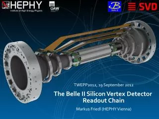
Readout System Concept • Prototype readout systemexists • Verified in several beam tests • Scheme shown below T. Bergauer (HEPHY Vienna)
Readout Chip: APV25 • Developed for CMS (LHC) by Imperial College London and Rutherford Appleton Lab • 70.000 chips installed • 0.25 µm CMOS process (>100 MRad tolerant) • 128 channels • 192 cell analog pipeline no dead time • 50 ns shaping time low occupancy • Noise: 250 e + 36 e/pF must minimize capacitive load!!! • Multi-peak mode (read out several samples along shaping curve) • Thinning to 100µm successful T. Bergauer (HEPHY Vienna)
Prototypes Repeater Box Level translation, buffering FADC+PROC (9U VME) Digitization, zero-suppression, hit time reconstruction T. Bergauer (HEPHY Vienna)
APV25 – Hit Time Reconstruction • Possibility of recording multiple samples (x) along shaped waveform (feature of APV25) • Reconstruction of peak time (and amplitude)by waveform fit • Offline now • Hardware later • Is used toremove off-timebackground hits Measurement T. Bergauer (HEPHY Vienna)
Occupancy Reduction T. Bergauer (HEPHY Vienna)
Belle and Belle II SVDDouble Sided SensorsReadout SystemChip-on-Sensor-ConceptSummary T. Bergauer (HEPHY Vienna)
Chip-on-Sensor Concept • Chip-on-sensor concept for double-sided readout • Flex fan-out pieces wrapped to opposite side (hence “Origami“) • All chips aligned on one side single cooling pipe Side View (below) T. Bergauer (HEPHY Vienna)
Origami Module with 6” HPK DSSD T. Bergauer (HEPHY Vienna)
Origami Module Assembly Ingredients: • DSSD sensors • Kapton PCB and pitch-adapters • APV Readout chips Followed by complicated assembly procedure • currently verified by all groups interested in ladder assembly T. Bergauer (HEPHY Vienna)
Sketch of the Outermost Ladder (Layer 6) • Composed of 5 x 6” double-sided sensors • Center sensors have Origami structure • Averaged material budget over the full module: 0.55% X0 ca. 60cm T. Bergauer (HEPHY Vienna)
Carried by ribs made of carbon fiber and Airex foam Very stiff, yet lightweight thanks to the sandwich construction Ladder Mechanics Cooling Pipe Sensor Support Ribs T. Bergauer (HEPHY Vienna)
CO2Cooling • Closed CO2 cooling plant under development • Collaboration with CERN • First step is to gain experience with open (blow) system Control cabinet with touch screen Accumulator 1.6 m 1.2 m 1.3 m Liquid pumps T. Bergauer (HEPHY Vienna)
Belle and Belle II SVDDouble Sided SensorsReadout SystemChip-on-Sensor-ConceptSummary T. Bergauer (HEPHY Vienna)
Summary • KEKBis the highest luminosity machine in the world • Upgradeof KEKB and Belle (2010-2014) • 40-fold increase in luminosity • Needs upgrades of all sub-detectors • New, enlarged Silicon Vertex Detector • DEPFETpixel double-layer • Four double-sided striplayers • Strip Detector R&D • 6inch Double Sided Strip Detectors by HPK and Micron • Optimal p-stop geometry identified by SNR measurements before and after irradiation • Readout with hit time reconstruction for improved background tolerance • Origamichip-on-sensor concept for low-mass DSSD readout T. Bergauer (HEPHY Vienna)
Backup Slides follow The End. T. Bergauer (HEPHY Vienna)
New IR with crab crossing and smaller by* Crab cavity 8GeV e- 3.5GeV e+ More RF for higher beam current New beam-pipes with ante-chamber Damping ring for e+ beam SR KEKB accelerator upgrade T. Bergauer (HEPHY Vienna)
Faster calorimeter with waveform sampling and pure CsI (endcap) Background tolerant super small cell tracking detector Si vertex detector with high background tolerance (+2 layers, pixels) Belle-II KL/m detection with scintillator and next generation photon sensors New particle identifier with precise Cherenkov device: (i)TOP or fDIRC. Endcap: Aerogel RICH New dead-time-free pipelined readout and high speed computing systems T. Bergauer (HEPHY Vienna)
Sensor Types and Vendors T. Bergauer (HEPHY Vienna)
Micron Wafer Layout 3 different GCDsfor the n-side Quadratic baby sensors 2,3,4 p-side: 512 strips 50 µm pitch 1 interm. strip n-side: 256 strips 100 µm pitch 0 interm. strip different p-stop patterns Main sensor p-side: 768 strips 75-50 µm pitch 1 interm. strip n-side: 512 strips 240 µm pitch 1 interm. strip combined p-stop Teststructures for p-side 1) atoll p-stop varying distance from strip 2) conventional p-stop varying width 3) combined p-stop varying distance from strip Baby sensor 1 p-side: 512 strips 50 µm pitch 1 interm. strip n-side: 512 strips 100 µm pitch 1 interm. strip atoll p-stop 1) 2) 3) Teststructures for n-side(no GCD) T. Bergauer (HEPHY Vienna)
p-stop layouts of the test sensors • Three different p-stop patterns • Per pattern, four zones with different geometry • Green: strip implant (n), Red: p-stop T. Bergauer (HEPHY Vienna)
eta distribution for atoll p-stop Charge accumulation in unimplanted region T. Bergauer (HEPHY Vienna)
Current Barrel Layout Origami Cooling Tubes Slanted Sensors Hybrid Boards T. Bergauer (HEPHY Vienna)
Comparison VA1TA – APV25 VA1TA (SVD) • Commercial product (IDEAS) • Tp = 800ns (300 ns – 1000 ns) • no pipeline • <10 MHz readout • 20 Mrad radiation tolerance • noise: ENC = 180 e + 7.5 e/pF • time over threshold: ~2000 ns • single sample per trigger • APV25 (Belle-II SVD) • Developed for CMS by IC London and RAL • Tp = 50 ns (30 ns – 200 ns) • 192 cells analog pipeline • 40 MHz readout • >100 Mrad radiation tolerance • noise: ENC = 250 e + 36 e/pF • time over threshold: ~160 ns • multiple samples per trigger possible (Multi-Peak-Mode) T. Bergauer (HEPHY Vienna)
Origami Module (TDC error subtracted) Measured Hit Time Precision • Results achieved in beam tests with several different types of Belle DSSD prototype modules (covering a broad range of SNR) • 2...3 ns RMSaccuracy at typical cluster SNR(15...25) • Working onimplementationin FPGA (using lookup tables) – simulationsuccessful T. Bergauer (HEPHY Vienna)
Maximum Radiation Length Distribution APV Kapton Pipe Coolant Sensor CFRP Rohacell T. Bergauer (HEPHY Vienna)
Cooling Boundary Conditions • Power dissipation per APV: 0.35 W • 1 Origamisensorfeatures 10 APVs • Total Origami power dissipation: 312 W • 354 W dissipated at the hybrid boards • Total SVD power dissipation: 666 W T. Bergauer (HEPHY Vienna)