Download
1 / 56
560 likes | 582 Views
This chapter explores manipulations in photoinjectors, space-charge compensation, flat beam generation, emittance exchange, and collimation in linacs and storage rings for electron beams. It also discusses the requirements and techniques for shaping and preserving beam emittance in photoinjectors.

E N D
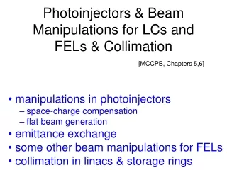
Photoinjectors & Beam Manipulations for LCs and FELs & Collimation [MCCPB, Chapters 5,6] • manipulations in photoinjectors • space-charge compensation • flat beam generation • emittance exchange • some other beam manipulations for FELs • collimation in linacs & storage rings
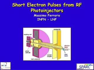
sources of electron beams requirements: small emittance high charge, high repetition rate, possibly high degree of polarization • thermionic guns • dc guns with laser photocathodes • photo-cathode rf guns (SLC) rf wave e- laser beam
cross section of an early BNL S-band rf gun (J. Clendenin, 1996)
rf photo-injector most popular in modern e- accelerators (in particular, if low emittances are desired); high-power pulsed laser illuminates photocathode placed on the end wall of an accelerating cavity, electrons are immediately accelerated in rf field normalized emittance determined by three effects: • thermal emittance – initial transverse momenta • rf emittancee – from time-dependent focusing force • space-charge force techniques for shaping and preserving the beam emittance from such injector: space-charge compensation using solenoids generation of a flat-beam transverse-longitudinal emittance exchange
transverse view space-charge compensation longitudinal bunch profile radius a assume transverse uniform distribution with radius a z space-charge force if l(z) not constant, different longitudinal slices will experience different focusing force Fr x’ different slices rotate at different speed projected emittance is increased x
x: normalized longitudinal coordinate r: normalized transverse coordinate after drift of length s: depends on shape of distribution assume L constant ‘space-charge compensation” (B. Carlsten, ~1993) place lens of focal length f after distance zl after total distance zd+zl: bunch slices are realigned emittance is indeed 0 at chosen value of f in reality L not constant but above scheme reduced the emittance by a factor 10 in Los Alamos studies
after first drift after solenoid center edge ra after final drift all particles are on one line!
beware of bifurcation! r’ “crossover” r’ r r strong space charge bunch center weak space charge phase-space bifurcation bunch edge important design criterion for photo-injectors: minimize fraction of beam crossing over! similar techniques to correct correlated growth in projected emittance due to nonlinear force can be applied elsewhere
flat-beam transformation • proposed by Y. Derbenev to convert round beam into flat or vice versa (1998) • in particular can produce a flat beam from a photoinjector if source is placed in solenoid field and afterwards passed through a (skew) FODO channel with p/2 different phase advance in x & y
kick at exit of solenoid phase-space vector at exit of solenoid this is a flat beam tilted by 45 degree! if we use skew-quad. channel, could get a flat beam in x quadrupole channel with phase advance difference p/2 in x and y choose b=1/k
however initial beam has also some rms slope (temperature) assuming product of x and y emittances approximately conserved experimental tests at Fermilab A0 line demonstrated the feasibility of this scheme
FNAL Flat Beam Experiment schematic layout simulated evolution of transverse emittances along the FNPL beamline for standard nominal settings Y.-E. Sun
FNAL Flat Beam Experiment – cont’d Overview of the RFTB section. The letters N, S and X represents normal and skew quadrupoles, and diagnostic stations. Dimension are in mm. measured simulated Simulated and measured beam transverse density evolution. The consecutive plots corresponds to location X3, X4, X5, X6, X7 and X8. Dimensions are in mm. Y.-E. Sun
general emittance exchange between two planes which can be rewritten as with l2 magnitude of the coupling and is the sum of the squares of the four elements of the normalized coupling block of the transfer matrix, i.e. U: where and M. Cornacchia and P. Emma
equal initial uncoupled emittances will always remain equal through a symplectic map; similarly, equal uncoupled emittances cannot be generated from unequal uncoupled initial emittances - setting |A| = 1/2 produces equal emittances, but they are then highly coupled with 𝜆2≠0
transverse to longitudinal emittance exchange - EEX • proposed by M. Cornacchia and P. Emma to reduced the transverse emittance (and also shrink the bunch length) for FELs (2002) • realized by placing a transverse deflecting mode radio-frequency cavity (“crab cavity”) in a magnetic chicane
M. Cornacchia and P. Emma Initial (top) and final (bottom) phase space tracking plots. The horizontal and longitudinal emittances are completely exchanged, as predicted.
transverse to longitudinal emittance exchange – experimental EEX demonstration at FNAL A0 line Layout of the A0 Photoinjector with straight ahead and EEX beamline sections. T. Koeth, 2009
EEX - key ingredients 1. half chicane (dipole magnets) creates correlations between x and d 2. deflecting cavity changes energy of particles with transverse offset x and d, and deflects particles horizontally depending on the longitudinal position 3. another half chicane thin lens deflecting cavity P. Emma and M. Cornacchia
The 4x4 (horizontal-longitudinal) emittance exchange matrixas a function of TM110 cavity strength. The cavity is off at k=0% and is energized to the ideal emittance exchange strength at k=100%. The circles are measured points, the green (lighter) lines are fits to the data, and the red (darker) lines are calculated values. T. Koeth, 2009
the 4x4 (horizontal-longitudinal) measured matrix calculated matrix elements nonzero due to finite cavity length T. Koeth, 2009
Transverse input parameters were tuned (by adjusting input quadrupoles) for a minimum output bunch-length energy-spread product. Relative output 1/σp·σz product map against input quadrupole currents. The white cross hairs indicate a choice for EEX operation. Calculated ratio of εx,in/(σp·σz)out over input quad scan. The white and green cross hairs indicate the operating points for Feb 6 and Feb 11 data sets respectively. T. Koeth
February 11, 2009, Direct EEX Data Set, Reflecting Input and Output rms Normalized Emittances T. Koeth, 2009
P. Schmüser Undulator Radiation
Undulators & Free Electron Lasers Z. Huang, P. Schmuser undulator undulator parameter fundamental wavelength of undulator radiation in forward direction condition for sustained energy transfer from electron to light wave
Z. Huang, P. Schmuser linac based X-ray FEL - LCLS 1-D power gain length P. Emma, PAC09 Pierce parameters e- density saturation power typical requirements exponential growth and saturation of the FEL power in SLAC LCLS at l=0.15 nm; initiated by Self Amplified Spontaneous Emission (SASE) process
combination flat-beam gun & EEX standard rf photocathode gun: gex,ygun~ 1 mm, gezgun ~ 0.1 mm flat beam scheme: (gex,, gey,gez) → (10, 0.1, 0.1) mm followed by transverse-to-longitudinal exchange: (gex,, gey,gez) → (0.1, 0.1, 10) mm with much improved FEL performance (3x shorter undulator) l=0.4 Å P. Emma et al, 2006
SASE and seeded FEL - FLASH P. Schmuser et al. FEL power as a function of z/Lg0 (1D power gain length) in a seeded FEL and a SASE FEL (soft X-ray FEL FLASH)
FEL seeding • SASE exhibits shot-to-shot fluctuations in wavelength and limited • coherence length (many uncorrelated spikes along the bunch length) • various seeding methods proposed to improve coherence • length of SASE radiation: • High harmonic generation (HHG) in gas; VUV • Self seeding: SASE signal produced by short undulator passed • through monochromator and serves as seed radiation • for main undulator • High-gain harmonic generation (HGHG) electron is energy-modulated • by interaction in an undulator by interaction with powerful laser; • magnetic chicane converts energy modulation into density • modulation; then second undulator for coherent emission from • density modulated beam at higher harmonic frequency • Echo enabled harmonic generation (EEHG): second modulator followed • by second chicane; electron beam interacts twice with two laser • pulses in two modulators; density modulation at a very high • harmonic number
HGHG FEL scheme laser R56 e- shift by l/4 modulator radiator D. Xiang G. Stupakov phase space distribution
EEHG FEL scheme laser w1 laser w2 R56(1) R56(2) modulator 1 radiator Modulator 2 e- shift by >10l current distribution phase space distribution D. Xiang G. Stupakov
what happens in a modulator? laser A.A. Zholends, M.S. Zolotorev, PRL 76, 6 (1996) total electric field laser radiation spontaneous undulator radiation total field energy f: relative phase of the laser light wave and electron wiggling trajectory in undulator spontaneous radiation of electrons in an undulator
→ amplitude of e- energy modulation after the modulator A.A. Zholends, M.S. Zolotorev, PRL 76, 6 (1996) an alternative formula can be found in Z. Huang et al. PRST-AB 7, 074401 (2004) • applications of modulators: • laser heating (suppression of microbunching • instability in bunch compressors), e.g. for FELs • FEL HGHG • FEL EEHG • femtosecond pulse generation (bunch “slicing”) • in storage rings • …
femtosecond pulse generation at the ALS R.W. Schoenlein et al, SCIENCE, Vol. 287 March 2000 Transverse separation of modulated electrons in dispersive bend of the storage ring Separation of femtosecond synchrotron radiation at the beamline image plane. Laser interaction with electron bunch in a resonantly tuned wiggler. electron bunch distribution (as a function of horizontal displacement Dx and time) at the radiating bend magnet, following inter-action with the laser pulse in the wiggler, and propagation through 1.5 arc sectors of the storage ring E=1.5 GeV, sE=1.2 MeV Mu=19 periods, lu=16 cm, K=13, tL=100 fs, AL=400 mJ, lL=800 nm
collimation • removal of beam halo, which otherwise causes background in the detector (el.-magnetic showers or muon production when lost near detector; or synchrotron radiation when passing at large amplitudes) or, for s.c. proton rings, could quench the magnets • controlled removal (activation of only one area) • multistage systems frequently employed • collimators also serve to protect the rest of the accelerator against catastrophic beam losses due to failure (machine protection) • collimator survival collimator impedance challenge for many future projects
example: collimator at the SNS high-energy beam-transfer line
collimation in linear colliders beam usually not of ideal shape • beam-gas Coulomb scattering • beam-gas bremsstrahlung • Compton scattering off thermal photons • linac wake fields • halo from the source or from damping rings • halo from ring-to-linac transport and bunch compression,…
Is there halo in linear colliders? Yes, measured beam distribution at the end of the SLAC linac (projection on the x-y plane)!
More Complete List of Candidate Processes Dispersion Space charge (?) Elastic scattering off residual gas Residual-gas bremsstrahlung Touschek scattering Intrabeam scattering Dark currents Nonlinear magnetic fields Scattering off thermal photons Scattering off laser field Incoherent & nonl. wake fields Synchrotron radiation (coherent & incoherent) Ion or electron-cloud effects linac close to the source, in bends everywhere everywhere everywhere everywhere cavities, linac ring, linac scattering photo gun e.g. collimators in bends e- or e+ beams
at the SLC • muons, SR, showers were all problems • more and more collimators were added over the years upstream of the final focus • magnetized toroids were placed between collimators and collision points to reduce the number of muons reaching the detector • it was difficult to model the halo
collimation is done for different betatron phases and in energy schematic of a collimation system for future linear colliders consisting of spoiler and absorber pairs scattering off thin spoiler increases beam size on subsequent absorber to prevent damage
collimation in storage rings halo generating processes • beam-gas Coulomb scattering • beam-gas bremsstrahlung • Compton scattering off thermal photons • nonlinear fields (resonances, tune drifts,…) • space charge • intrabeam scattering, Touschek effect • beam-beam interaction
measurement of beam tails in LEP-2 (80-100 GeV) using movable collimators result of Monte-Carlo simulation (Courtesy H.. Burkhardt, 1998) beam-gas scattering and thermal-photon scattering
halo generation by scattering processes halo generation rate density of residual gas or of thermal photons cross section total cross section s depends on limits for d, q
Bremsstrahlung electrons lose energy in inelastic scattering events with the residual gas (e.g., SLAC-PUB-8012 and references therein) k: energy of photon radiated in bremsstrahlung event total cross section for energy loss > 1% is 6.5 barn for CO remains important at high energies
Elastic Coulomb scattering total cross section for scattering above minimum angle scattered electrons: scattering angle decreases at higher energies
at large amplitudes tail from elastic gas scattering like ~1/y3 Tor Rauben- heimer, 1992 damping ring