MICE Beamline Collimation and Correction
130 likes | 302 Views
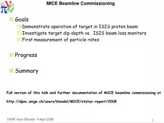
MICE Beamline Collimation and Correction. Tom Roberts Carol Johnstone Muons, Inc. Pion Segment. Our initial guess was that the target would dip about 2 mm into the ISIS beam, giving about 1.5e12 protons on target.

MICE Beamline Collimation and Correction
E N D
Presentation Transcript
MICE BeamlineCollimation and Correction Tom Roberts Carol Johnstone Muons, Inc. MICE Beamline Collimation and Correction
Pion Segment • Our initial guess was that the target would dip about 2 mm into the ISIS beam, giving about 1.5e12 protons on target. • Recent measurements of target rates indicate that the target will need to dip significantly deeper into the beam. • So the question arises: how important are the vertical position and extent of the target? • The following analysis uses G4beamline to model pi+ production through the Decay Solenoid, using: • A target that is 2 mm high, 5.2 mm wide (10*sin(25˚)+1*cos(25˚)) • A wide and flat thin window in the target box – this is studying the optics, not the actual Target Box window. • Decays are disabled • The basic figure-of-merit is the number of π+ that make it through the Decay Solenoid. MICE Beamline Collimation and Correction
Pion Segment and Decay SolenoidVertical Efficiency The 2mm target can be ±4 cm off axis (dotted lines) and π+ production remains >90% of the peak (for a wide window in the Target Box).The red lines are the radius of the Q1 aperture, the blue lines are the actual (rounded square) window in the Target Box. MICE Beamline Collimation and Correction
Pion SegmentVertical Position before Decay Solenoid Histograms of vertical position at the entrance to the Decay Solenoid. Q1-Q3 create an inverted image of the target at the entrance to the Decay Solenoid, with a magnification of ~0.4.The spotsize has tails from multiple-scattering. MICE Beamline Collimation and Correction
Pion Segment and Decay SolenoidHorizontal Efficiency The 5.2mm target can be ±2 cm off axis (dotted lines) and π+ production remains >90% of the peak (for a wide window in the Target Box).The blue lines are the actual (rounded square) window in the Target Boxminus the half-width of the target. MICE Beamline Collimation and Correction
Pion SegmentX vs Y Before Decay Solenoid X-Y scatter plot of protons, π+, and e+ just before the Decay Solenoid.The red ellipse is the aperture (x expanded to show detail).Q1-Q3 are apparently mis-tuned by a small amount. MICE Beamline Collimation and Correction
Pions inside the Decay Solenoid“Beam’s eye” view Aperture ~500 tracks X-Y orbits of π+ in the Decay Solenoid, for beamY +10 and -10 mm;for π+ that get at least 20 cm into the Decay Solenoid. MICE Beamline Collimation and Correction
Pion Segment – Conclusions • For pions that get through the window in the Target Box, the π+ production rate is almost independent of position. • This means the target intersection with the ISIS beam can be anywhere within ±3 cm of the beamline axis. • As the vertical acceptance of the optics is larger than the window, vertical correctors are not needed except for correction of mechanical misalignments (which are expected to be comparatively small). • The same is true for the horizontal optics. In addition, horizontal correctors would merely modify the selected pion momentum, and would complicate the calibration. There is no fine-tuning of a spot, the horizontal distribution is a continuum. • Collimators are not appropriate in the pion segment, as reducing the target depth does the same thing. • So we intend to propose no collimators or correctors in the pion segment. MICE Beamline Collimation and Correction
Pion Segment – Open Issue How can we tell whether or not the beamwe use clears the 30x30 mm windowin the Target Box? In particular: is there any method otherthan a careful survey? MICE Beamline Collimation and Correction
Muon Segment Collimators • Collimation to limit momentum spread • Should be at a momentum-dispersed focus • Only possibility is midway between Q6 and Q7 • Collimation to limit transverse emittance • Ideal: • two pairs of H and V collimators separated by an odd-integer of π/2 phase advance • Should be at low dispersion • Possible: • Vertical collimator should be ahead of Q4 (avoid quad apertures giving a tune-dependent collimation) • Horizontal collimator must be ahead of D2 (low dispersion) • Only possibility is inside D2 • The horizontal dispersion after D2 precludes any transverse-emittance collimation • A vertical collimator midway between Q6 and Q7 is appropriate MICE Beamline Collimation and Correction
Muon Segment Trims • Ideal: • Trims come in pairs separated by some distance, so both position and angle of the beam can be controlled • Trims are placed just after collimators • Horizontal Trims • Before momentum collimation just mimics D2 • Between momentum collimator and Q7 • Possibly another between Q9 and Tracker1 • Vertical Trims • After each vertical collimator • The one between D2 and Q4 may be difficult (access path) • Possibly another between Q9 and Tracker1 MICE Beamline Collimation and Correction
Current thinking, based on optics H and VCollimators(inside D2) H and VCollimators H and VTrims V Trim(if possible) H and V Trims(if possible) MICE Beamline Collimation and Correction
Next Steps • Pair of collimators inside D2 • Determine detailed requirements • Mechanical design • Pair of collimators between Q6 and Q7 • Consider interaction with beam stop, shielding, and quads • Look for existing units • Pair of trims between collimators and Q7 • Consider interaction with beam stop, shielding, and quads • Look for existing magnets • Other suggested components: • Check MICE drawings to consider possibilities • Put these new elements into G4beamline and investigate their performance. MICE Beamline Collimation and Correction