Download
1 / 24
550 likes | 1.26k Views
Spectroscopic Ellipsometry. University of Texas at El Paso Lynn Santiago Dr. Elizabeth Gardner Chem 5369. Ellipsometry – An Essential Tool for Characterizing Nanomaterials. “[The ellipsometry] methods are the workhorse analyses

E N D
Spectroscopic Ellipsometry University of Texas at El Paso Lynn Santiago Dr. Elizabeth Gardner Chem 5369
Ellipsometry – An Essential Tool for Characterizing Nanomaterials “[The ellipsometry] methods are the workhorse analyses of a laboratory, as they are used on almost every project involving surface chemistry, whether it be a silicon surface or a metal surface.” James, D.K., Tour, J.M.. Analytica Chimica Acta 568 (2006) 2-19
Spectroscopic Ellipsometry Introduction How it works Setup Light Source Components and Functions Equation Advantages Single Wavelength Ellipsometry Setup Components and Functions Advantages/Disadvantages Imaging Ellipsometry Setup Components and Functions Advantages/Disadvantages Outline
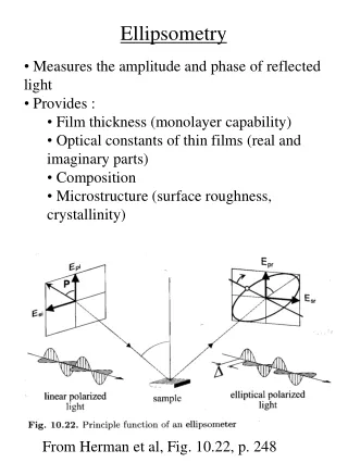
Introduction to Spectroscopic Ellipsometry • It is used for a variety of measurements: • Thickness of films. • Optical properties. • Modeling of surface roughness. • Ellipsometry is: • well known • non-destructive • precise • accurate • analytical technique
Using Ellipsometry to Characterize Nano-electronic-based Materials • The technique is used for the determination of physical properties of organic molecular electronic-based devices. • It is commonly used for the characterization of self-assembled monolayers (SAMS), substrates, polymers and thin layers. • It can probe molecular assemblies such as SAMS. • Doesn’t change their physical characteristics. • Determines whether you have single or multiple layers assembled on a surface.
How does ellipsometry work? • Light is shined from a light source. • The light is polarized by passing through a linear polarizer. • The light is then elliptically polarized by passing through a compensator. • The light hits the sample, is reflected and is linearly polarized. • The analyzer detects the change of polarization. • The detector catches the light and send it to the computer to process the data. • The measured data combined with computerized optical modeling gives information of the film thickness and refractive index values of a sample.
Multiple Wavelengths Unpolarized Light 5. Detector Linearly Polarized Light 1. Light Source 4. Analyzer 2. Linear Polarizer 3. Compensator Sample Elliptically Polarized Light Spectroscopic Ellipsometry Setup
Light Source • The light source consists of wavelengths in the following regions • Ultraviolet • 185nm – 260nm • Visible • 0.4nm – 0.7nm • Infrared • 0.7nm – 1.1μm http://www.flame-detection.net/flame_detector/flame_detection_school/flame_spectrum.htm
SWE Components and Functions 2. Polarizer - produces light in a special state of polarization at the output 3. Compensator - used to shift the phase of one component of the incident light • Depending on orientation, it transforms the ellipse of polarization • Linearly polarized light into elliptically polarized light when set to 45° in respect to the linear polarization axis. 4. Analyzer – second polarizer that detects the linearly polarized light reflected off the sample 5.Detector http://www.nanofilm.de/fileadmin/cnt_pdf/technology/Ellipsometry_principle__150dpi_s.pdf
Calculating Change in Polarization • This is the equation used to calculate the change in polarization. Ρ=Rp/Rs=tan(Ψ)eiΔ • Ρ = change in polarization • Rp = component oscillating in the plane of incidence • Rs = component is oscillating perpendicular to the plane of incidence • Tan Ψ = amplitude ratio of reflection • Δ = phase shift
rp rs What are Rp and Rs components? Rp = |rp|2 Rs = |rs|2
SE Advantages • No contact with the films is required for the analysis of films • Technique does not require a reference or standards • It provides both the phase and amplitude ratio of a sample • Analysis is less sensitive to the fluctuations of light intensity
Concentrating the Light Source We have seen that spectroscopic ellipsometry uses a range of wavelengths to analyze a sample. Now we will see an instrument that uses the same concept but uses one particular wavelength of light to analyze a sample.
Single Wavelength Ellipsometry • Also known as Laser Ellipsometry • Used in Imaging Ellipsometry • Uses a light source with a specific wavelength http://www.eas.asu.edu/nanofab/capabilities/metrology.html
One Wavelength Unpolarized Light 5. Detector Linearly Polarized Light 1. Light Source 4. Analyzer 2. Linear Polarizer 3. Compensator Sample Elliptically Polarized Light Single Wavelength Ellipsometry Setup
Light Source – This is a laser with a specific wavelength Commonly a HeNe laser with the wavelength of 632.8 nm SWE Light Source This is not from an ellipsometer but shows what a HeNe laser looks like. http://www.technology.niagarac.on.ca/courses/phtn1333/
Pros and Cons of SWE • Advantages: • Laser can focus on a specific spot • Lasers have a higher power than broad band light sources • Disadvantage: • Experimental output is restricted to one set of Ψ and Δ values per measurement
Taking it a Step Further Now there exists the technology to use ellipsometry and view a sample while it is being analyzed.
Imaging Ellipsometry • Combines SWE with Microscopy • High Lateral Resolution • Possible to see tiny samples • High contrast imaging capabilities to detect various properties of samples • surface defects • Inhomogenities • Provides spatial resolution for a variety of areas • Microanalysis • Microelectronics • Bio-analysis http://www.soem.ecu.edu.au/physics/physics_facilities.htm
Unpolarized Light CCD Camera Linearly Polarized Light Laser Light Source Analyzer Linear Polarizer Compensator Objective Sample Elliptically Polarized Light Imaging Ellipsometry Setup Two New Components
Imaging Components and Functions • Objective – images the illuminated area of the sample onto the camera • CCD Camera - a camera with an image sensor that is an integrated circuit made with light sensitive capacitors http://www.nanofilm.de/fileadmin/cnt_pdf/technology/Ellipsometry_principle__150dpi_s.pdf
Pros and Cons of Imaging Ellipsometry • Advantages: • Provides film thickness and refractive index • Provides a real time contrast image of the sample • Ability to restrict ellipsometric analysis to a particular region of interest within the field-of-view • The signal provided is spatially resolved to show the details of the sample • Disadvantages: • The inclined observation angle • Only a limited area of the image appears to be well-focused when using conventional optics
Acknowledgements • David Echevarría – Torres • Dr. Elizabeth Gardner
References • James, D.K., Tour, J.M.. Analytica Chimica Acta 568 (2006) 2-19. • Goncalves, D., Irene, E.A.. Quim. Nova, Vol. 25, No. 5, 794-800. • Nanofilm Surface Analysis • http://www.nanofilm.de/fileadmin/cnt_pdf/technology/Ellipsometry_principle__150dpi_s.pdf • http://www.wikipedia.org