Download
1 / 38
380 likes | 533 Views
COMP3221: Microprocessors and Embedded Systems. Lecture 22: Serial Input/Output (II) http://www.cse.unsw.edu.au/~cs3221 Lecturer: Hui Wu Session 2, 2004. Overview. USART (Universal Synchronous and Asynchronous serial Receiver and Transmitter) in AVR. Main Features of USART in AVR.

E N D
COMP3221: Microprocessors and Embedded Systems Lecture 22: Serial Input/Output (II) http://www.cse.unsw.edu.au/~cs3221 Lecturer: Hui Wu Session 2, 2004
Overview • USART (Universal Synchronous and Asynchronous serial Receiver and Transmitter) in AVR COMP3221/9221: Microprocessors and Embedded Systems
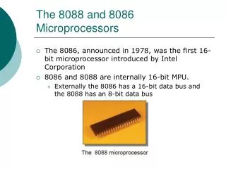
Main Features of USART in AVR • Full duplex operation (independent serial receive and transmit registers). • Asynchronous or synchronous operation. • Master or slave clocked synchronous operation. • High resolution baud rate generator. • Supports serial frames with 5, 6, 7, 8, or 9 data bits and 1 or 2 stop bits. • Odd or even parity generation and parity check supported by hardware.
Main Features of USART in AVR (Cont.) • Framing error detection. • Noise filtering includes false start bit detection and digital low pass filter. • Three separate interrupts on TX Complete, TX Data Register Empty and RX Complete. • Multi-processor communication mode. • Double speed asynchronous communication mode.
The Main Components of USART Three main components: • Clock generator • The Clock Generation logic consists of synchronization logic for external clock input used by synchronous slave operation, and the baud rate generator. • Transmitter • The Transmitter consists of a single write buffer, a serial Shift Register, Parity Generator and Control Logic for handling different serial frame formats. • The write buffer allows a continuous transfer of data without any delay between frames.
The Main Components of USART (Cont.) • Receiver • The Receiver is the most complex part of the USART module due to its clock and data recovery units. • The recovery units are used for asynchronous data reception. • In addition to the recovery units, the Receiver includes a Parity Checker, Control Logic, a Shift Register and a Two Level Receive Buffer (UDR). • The Receiver supports the same frame formats as the Transmitter, and can detect Frame Error, Data OverRun and Parity Errors.
Clock Generation • The Clock Generation logic generates the base clock for the Transmitter and Receiver. • The USART supports four modes of clock operation: Normal asynchronous, Double Speed asynchronous, Master synchronous and Slave synchronous mode. • The UMSEL bit in USART Control and Status Register C (UCSRC) selects between asynchronous and synchronous operation. • Double Speed (asynchronous mode only) is controlled by the U2X found in the UCSRB Register. • When using synchronous mode (UMSEL = 1), the Data Direction Register for the XCK pin (DDR_XCK) controls whether the clock source is internal (Master mode) or external (Slave mode). • The XCK pin is only active when using synchronous mode.
Clock Generation (Cont.) Signal description: txclk: Transmitter clock (internal signal). rxclk: Receiver base clock (internal signal). xcki: Input from XCK pin (internal signal). Used for synchronous slave operation. xcko: Clock output to XCK pin (internal signal). Used for synchronous master operation. fosc: XTAL pin frequency (system clock).
The Baud Rate Generator • The USART Baud Rate Register (UBRR) and the down-counter connected to it function as a programmable prescaler or baud rate generator. • The down-counter, running at system clock (fOSC), is loaded with the UBRR value each time the counter has counted down to zero or when the UBRRL Register is written. • A clock is generated each time the counter reaches zero. • This clock is the baud rate generator clock output (=fOSC/(UBRR+1)). • The transmitter divides the baud rate generator clock output by 2, 8, or 16 depending on mode. • The baud rate generator output is used directly by the receiver’s clock and data recovery units. However, the recovery units use a state machine that uses 2, 8 or 16 states depending on mode set by the state of the UMSEL, U2X and DDR_XCK bits.
Frame Formats • A serial frame is defined to be one character of data bits with synchronization bits (start and stop bits), and optionally a parity bit for error checking. • The USART accepts all 30 combinations of the following as valid frame formats: • 1 start bit • 5, 6, 7, 8, or 9 data bits • no, even or odd parity bit • 1 or 2 stop bits
Frame Formats (Cont.) • A frame starts with the start bit followed by the least significant data bit. Then the next data bits, up to a total of nine, are succeeding, ending with the most significant bit. • If enabled, the parity bit is inserted after the data bits, before the stop bits. When a complete frame is transmitted, it can be directly followed by a new frame, or the communication line can be set to an idle (high) state.
Frame Formats (Cont.) St Start bit, always low. (n) Data bits (0 to 8). P Parity bit. Can be odd or even. Sp Stop bit, always high. IDLE No transfers on the communication line (RxD or TxD). An IDLE line must be high.
Parity Bit Calculation • The parity bit is calculated by doing an exclusive-or of all the data bits. If odd parity is used, the result of the exclusive or is inverted. The relation between the parity bit and data bits is as follows: • Peven = dn dn-1 … d1 d0 0 • Podd = dn dn-1 … d1 d0 1 • Where PevenParity bit using even parity • Podd Parity bit using odd parity • dn Data bit n of the character • If used, the parity bit is located between the last data bit and first stop bit of a serial frame.
USART Initialisation • USART has to be initialised before any communication can take place. • The initialisation process normally consists of setting the baud rate, setting frame format and enabling the Transmitter or the Receiver depending on the usage. • For interrupt driven USART operation, the Global Interrupt Flag should be cleared when doing the initialisation.
USART Initialisation (Cont.) • Before doing a re-initialisation with changed baud rate or frame format, be sure that there are no ongoing transmissions during the period the registers are changed. • The TXC flag can be used to check that the Transmitter has completed all transfers, and the RXC flag can be used to check that there are no unread data in the receive buffer. Note that the TXC flag must be cleared before each transmission (before UDR is written) if it is used for this purpose.
USART Initialisation (Cont.) Assembly Code Example: USART_Init: ; Set baud rate out UBRRH, r17 out UBRRL, r16 ; Enable receiver and transmitter ldi r16, (1<<RXEN)|(1<<TXEN) out UCSRB,r16 ; Set frame format: 8data, 2stop bit ldi r16, (1<<USBS)|(3<<UCSZ0) out UCSRC,r16 ret
The USART Transmitter • The USART Transmitter is enabled by setting the Transmit Enable (TXEN) bit in the UCSRB Register. • When the Transmitter is enabled, the normal port operation of the TxD pin is overridden by the USART and given the function as the transmitter’s serial output. • The baud rate, mode of operation and frame format must be set up once before doing any transmissions. If synchronous operation is used, the clock on the XCK pin will be overridden and used as transmission clock.
The USART Transmitter (Cont.) • A data transmission is initiated by loading the transmit buffer with the data to be transmitted. • The CPU can load the transmit buffer by writing to the UDR I/O location. • The buffered data in the transmit buffer will be moved to the Shift Register when the Shift Register is ready to send a new frame. • The Shift Register is loaded with new data if it is in idle state (no ongoing transmission) or immediately after the last stop bit of the previous frame is transmitted. • When the Shift Register is loaded with new data, it will transfer one complete frame at the rate given by the baud register, U2X bit or by XCK depending on mode of operation.
The USART Transmitter (Cont.) Assembly Code Example: USART_Transmit: ; Wait for empty transmit buffer sbis UCSRA,UDRE rjmp USART_Transmit ; Put data (r16) into buffer, sends the data out UDR,r16 ret
Transmitter Flags and Interrupts • The USART Transmitter has two flags that indicate its state: USART Data Register Empty (UDRE) and Transmit Complete (TXC). Both flags can be used for generating interrupts. • The Data Register Empty (UDRE) flag indicates whether the transmit buffer is ready to receive new data. • This bit is set when the transmit buffer is empty, and cleared when the transmit buffer contains data to be transmitted that has not yet been moved into the Shift Register. For compatibility with future devices, always write this bit to zero when writing the UCSRA Register.
Transmitter Flags and Interrupts (Cont.) • When the Data Register empty Interrupt Enable (UDRIE) bit in UCSRB is written to one, the USART Data Register Empty Interrupt will be executed as long as UDRE is set (provided that global interrupts are enabled). UDRE is cleared by writing UDR. • When interrupt-driven data transmission is used, the Data Register Empty Interrupt routine must either write new data to UDR in order to clear UDRE or disable the Data Register Empty Interrupt, otherwise a new interrupt will occur once the interrupt routine terminates. • The Data Register Empty (UDRE) flag indicates whether the transmit buffer is ready to receive new data.
Transmitter Flags and Interrupts (Cont.) • When the Data Register empty Interrupt Enable (UDRIE) bit in UCSRB is written to one, the USART Data Register Empty Interrupt will be executed as long as UDRE is set (provided that global interrupts are enabled). UDRE is cleared by writing UDR. • When interrupt-driven data transmission is used, the Data Register Empty Interrupt routine must either write new data to UDR in order to clear UDRE or disable the Data Register Empty Interrupt, otherwise a new interrupt will occur once the interrupt routine terminates. • The Data Register Empty (UDRE) flag indicates whether the transmit buffer is ready to receive new data.
Transmitter Flags and Interrupts (Cont.) • The Transmit Complete (TXC) flag bit is set to one when the entire frame in the Transmit Shift Register has been shifted out and there are no new data currently present in the transmit buffer. • The TXC flag bit is automatically cleared when a transmit complete interrupt is executed, or it can be cleared by writing a one to its bit location. • The TXC flag is useful in half-duplex communication interfaces (like the RS-485 standard), where a transmitting application must enter Receive mode and free the communication bus immediately after completing the transmission.
The USART Receiver • The USART Receiver is enabled by writing the Receive Enable (RXEN) bit in the UCSRB Register to one. • When the Receiver is enabled, the normal pin operation of the RxD pin is overridden by the USART and given the function as the receiver’s serial input. • The baud rate, mode of operation and frame format must be set up once before any serial reception can be done. • If synchronous operation is used, the clock on the XCK pin will be used as transfer clock.
The USART Receiver (Cont.) • The Receiver starts data reception when it detects a valid start bit. • Each bit that follows the start bit will be sampled at the baud rate or XCK clock, and shifted into the Receive Shift Register until the first stop bit of a frame is received. • A second stop bit will be ignored by the Receiver. • When the first stop bit is received, i.e., a complete serial frame • is present in the Receive Shift Register, the contents of the Shift Register will be moved into the receive buffer. The receive buffer can then be read by reading the UDR I/O location.
The USART Receiver (Cont.) Assembly Code Example: USART_Receive: ; Wait for data to be received sbis UCSRA, RXC rjmp USART_Receive ; Get and return received data from buffer in r16, UDR ret
Receive Compete Flag and Interrupt • The Receive Complete (RXC) flag indicates if there are unread data present in the receive buffer. • This flag is one when unread data exist in the receive buffer, and zero when the receive buffer is empty (i.e. does not contain any unread data). • If the receiver is disabled (RXEN = 0), the receive buffer will be flushed and consequently the RXC bit will become zero. • When the Receive Complete Interrupt Enable (RXCIE) in UCSRB is set, the USART Receive Complete Interrupt will be executed as long as the RXC flag is set (provided that global interrupts are enabled). • When interrupt-driven data reception is used, the receive complete routine must read the received data from UDR in order to clear the RXC flag; otherwise a new interrupt will occur once the interrupt routine terminates.
Receiver Error Flags The USART Receiver has three error flags: Frame Error (FE), Data OverRun (DOR) and USART Parity Error (UPE). • The Frame Error (FE) flag indicates the state of the first stop bit of the next readable frame stored in the receive buffer. • The FE flag is zero when the stop bit was correctly read (as one), and the FE flag will be one when the stop bit was incorrect (zero). • This flag can be used for detecting out-of-sync conditions, detecting break conditions and protocol handling.
Receiver Error Flags (Cont.) • The Data OverRun (DOR) flag indicates data loss due to a receiver buffer full condition. • A Data OverRun occurs when the receive buffer is full (two characters), it is a new character waiting in the Receive Shift Register, and a new start bit is detected. • If the DOR flag is set there was one or more serial frame lost between the frame last read from UDR, and the next frame read from UDR. • The USART Parity Error (UPE) flag indicates that the next frame in the receive buffer had a Parity Error when received.
Asynchronous Data Reception • The USART includes a clock recovery and a data recovery unit for handling asynchronous data reception. • The clock recovery logic is used for synchronizing the internally generated baud rate clock to the incoming asynchronous serial frames at the RxD pin. • The data recovery logic samples and low pass filters each incoming bit, thereby improving the noise immunity of the Receiver. • The asynchronous reception operational range depends on the accuracy of the internal baud rate clock, the rate of the incoming frames, and the frame size in number of bits.
Asynchronous ClockRecovery • The Clock Recovery logic synchronizes internal clock to the incoming serial frames. • The following figure illustrates the sampling process of the start bit of an incoming frame. • The sample rate is 16 times the baud rate for Normal mode, and eight times the baud rate for Double Speed mode.
Asynchronous ClockRecovery (Cont.) • The horizontal arrows illustrate the synchronization variation due to the sampling process. Note the larger time variation when using the Double Speed mode (U2X = 1) of operation. • Samples denoted by zero are samples done when the RxD line is idle (i.e., no communication activity). • When the Clock Recovery logic detects a high (idle) to low (start) transition on the RxD line, the start bit detection sequence is initiated.
Asynchronous ClockRecovery (Cont.) • Let sample 1 denote the first zero-sample as shown in the figure. The Clock Recovery logic then uses samples 8, 9 and 10 for Normal mode, and samples 4, 5 and 6 for Double Speed mode (indicated with sample numbers inside boxes on the figure), to decide if a valid start bit is received. • If two or more of these three samples have logical high levels (the majority wins), the start bit is rejected as a noise spike and the Receiver starts looking for the next high to low-transition. • If however, a valid start bit is detected, the clock recovery logic is synchronized and the data recovery can begin. • The synchronization process is repeated for each start bit.
Asynchronous DataRecovery • When the receiver clock is synchronized to the start bit, the data recovery can begin. • The data recovery unit uses a state machine that has 16 states for each bit in Normal mode and eight states for each bit in Double Speed mode. The following figure shows the sampling of the data bits and the parity bit. Each of the samples is given a number that is equal to the state of the recovery unit.
Asynchronous DataRecovery (Cont.) • The decision of the logic level of the received bit is taken by doing a majority voting of the logic value to the three samples in the centre of the received bit. • The centre samples are emphasized on the figure by having the sample number inside boxes. • The majority voting process is done as follows: • If two or all three samples have high levels, the received bit is registered to be a logic 1. • If two or all three samples have low levels, the received bit is registered to be a logic 0. • This majority voting process acts as a low pass filter for the incoming signal on the RxD pin. • The recovery process is then repeated until a complete frame is received.
Reading • USART. Mega64 Data Sheet. COMP3221/9221: Microprocessors and Embedded Systems