Ethernet CSMA
Ethernet 1-2-3. Originated from a project by Digital, Intel, and XeroxThe most popular LAN standard in the worldConnects 80% of LAN devicesThe IEEE (Institute for Electrical and Electronics Engineers) 802.3 CSMA/CD (Carrier Sensing Multiple Access with Collision Detection) committee now forms and

Ethernet CSMA
E N D
Presentation Transcript
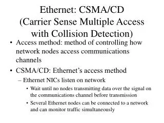
1. Ethernet (CSMA/CD) Overview
2. Ethernet 1-2-3 Originated from a project by Digital, Intel, and Xerox
The most popular LAN standard in the world
Connects 80% of LAN devices
The IEEE (Institute for Electrical and Electronics Engineers) 802.3 CSMA/CD (Carrier Sensing Multiple Access with Collision Detection) committee now forms and administers Ethernet standards
The unit of data traveling on Ethernet is called frame (many variations in structure)
Ethernet and CSMA/CD can be used interchangeably
Implemented on NICs (Network Interface Cards)
Ethernet technology is at the physical and data link layers
3. Ethernet Standards
4. Ethernet and OSI Model
5. IEEE 802.3 CSMA/CD Protocol Implemented in the Data Link Layer (Layer 2)
Rule #1: Do not talk if someone else is speaking
If a NIC does not hear another station sending, it may transmit
If another station is transmitting, a NIC must wait until no station is transmitting
Rule #2: Wait if two or more try to talk at the same time
Occasionally, two or more stations transmit at the same time (collision)
All involved stations stop transmitting and wait for a random amount of time
When the wait is over, follow Rule#1
The during of the random wait increase if the collision occurs again
After 16 collisions and random wait, the NIC gives up trying to deliver the frame
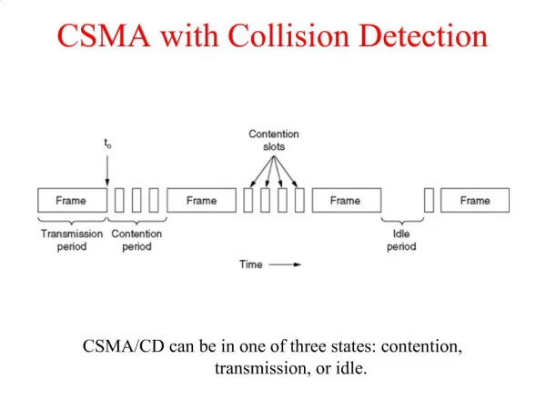
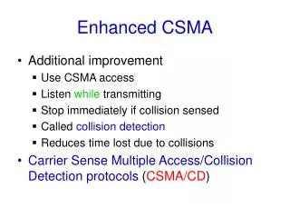
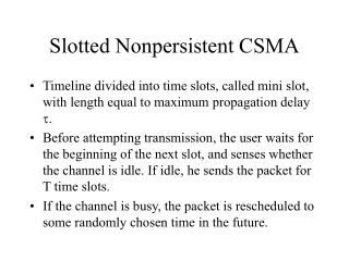
6. CSMA
7. Collision Detection
8. Ethernet Frame Formats Ethernet Version II
Original format
Include a 2-byte Type field to indicate higher-layer (the Network Layer) protocol carried inside the frame
IEEE 802.3
Novell uses this format
The 2-byte Type field was replaced by the length field
IEEE 802.3 with 802.2 LLC (Logical Link Control)
IEEE 802.3 with SNAP (SubNetwork Access Protocol)
9. Ethernet Version II Format
10. Version II Example
11. Explanation of the Example Destination address
The MAC address of the device the frame is intended for
An address of FF FF FF FF FF FF means broadcasting � will be discussed with ARP (Address Resolution Protocol)
Source address
NIC address of the sending machine
Type
�81 37� means Novell traffic
12. Ethernet Cabling Options Dealing with the Physical Layer (Layer 1)
Cabling specifications
Topologies: (the order in which stations receive bits)
Connectors
10Mbps
10Base5
10Base2
10baseT
10BaseFL
100Mbps
100BaseTX
100BaseT4
100BaseFX (multimode Fiber Optic)
Gigabit Ethernet
13. 10Base5 Ethernet
14. Characteristics of 10Base5 Ethernet Uses a large coaxial cable
Stations are connected to the cable using a vampire tap
A transceiver or MAU (medium attachment unit) is mounted on the vampire tap
An AUI (attachment interface unit) cable runs from the transceiver to the station
Coaxial cable is installed in a bus topology (straight line) with a 50W terminator. One end should be grounded
Can have up to 100 stations, up to 500 meters
The LAN fails if there is one break in the cabling system
15. 10Base2 Ethernet
16. Characteristics of 10Base2 Ethernet Uses thinner cable (RG58)
BNC T-connectors are used
Cabling is configured in a bus topology
Each of the cable is terminated with a 50W terminator
Up to 30 stations cab be attached
Cabling cannot exceed 185 meters (607 feet) in total length for a segment
A single cable fault causes total LAN failure
17. 10BaseT Ethernet
18. Characteristics of 10BaseT Ethernet UTP (unshielded Twisted Pairs) cabling, category 3 or higher, is installed
A hub and NIC are used to connect devices
Has a 100-meter distance limitation
RJ45 connectors are used on the hubs and NICs
Pins 1, 2, 3, and 6 are used on the RJ45 connectors
If one cable breaks, only that connection is affected
Patch panels and wall jacks are used to facilitate moves, additions, or changes
19. 10BaseFL Ethernet (Fiber Link)
20. Characteristics of 10BaseFL Ethernet Can be used to connect end users or as background connection
Use duplex connections (two strands of fiber)
Uses multimode fiber optic cable
Supports distances of 2,000 meters
Connects the transmit port of one device to the receive port of the other component on both ends
21. Ethernet Hubs Hubs receiving the bit stream from the transmitting device
Hubs examine the incoming bit stream, resynchronize each bit, and flood the bit stream to the other posts on the collision domain at 100 percent strength
22. 10Mbps Ethernet Design: The 5-4-3 Rule