Download
1 / 46
460 likes | 557 Views
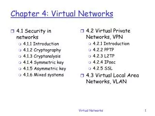
Explore the concept of overlay networks in computer networks, how they are built on top of the physical topology, and their applications for routing and performance improvement. Learn about Unicast Routing Overlay, Resilient Overlay Network (RON), and Multicast Overlay. Understand the benefits, challenges, and potential problems associated with overlay networks.

E N D
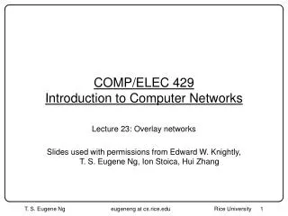
COMP/ELEC 429Introduction to Computer Networks Lecture 23: Overlay networks Slides used with permissions from Edward W. Knightly, T. S. Eugene Ng, Ion Stoica, Hui Zhang
Abstract View of the Internet • A collection of IP routers and point-to-point physical links connecting routers • Point-to-point links between two routers are physically as direct as possible • A copper wire, a coax cable or a fiber laid from one router to another
Reality • Fibers and wires are laid with tremendous physical constraints • You can’t just dig up the ground everywhere and lay fibers • Right-of-way issue • Most fibers are laid along railroads • Physical fiber topology often very far from the topology you want • IP Internet is over-laid on top of this physical fiber topology • IP Internet topology is only logical! • Concept: IP Internet is an overlay network
IP logical link Circuit E.g. An IP logical link overlaid on a circuit
Made Possible by Layering • Layering hides the detail of lower layer from higher layer • IP operates on datalink layer (say ATM or SONET) logical topology • ATM/SONET creates point-to-point circuits on the fibers Host A Host B Application Application Presentation Presentation Session Session Router Transport Transport Network Network Network Datalink Datalink Datalink Physical Physical Physical Physical medium
Overlay • Overlay is clearly a general concept • You can keep overlaying one network on another, it’s all logical • IP Internet overlays on top of physical topology • Why stop here? • Something else can overlay on top of IP Internet • Use IP tunnels to create yet another logical topology • E.g. VPNs
Advanced Reasons to Overlay On IP Internet • IP provides basic best effort datagram service • Many things you may want in a network but not supported • Like what? • Multicast • Reliable performance-based routing • More… e.g. content addressing and distribution • Can you build can overlay network on IP Internet to provide QoS? • How? • Overlay links must have guaranteed performance characteristics, otherwise, the overlay network cannot guarantee anything!
Unicast Routing Overlay • Internet routing is built upon Intra-domain and Inter-domain router protocols • OSPF/RIP; BGP • OSPF/RIP routing based on shortest link weight routing • Link weights are typically very static • Does not necessarily give you best performance path (delay, throughput, loss rate) • BGP routing based mostly on policy • Policy may have nothing to do with performance • BGP very slow to react to failure (no reaction to high loss rate, e.g.)
Resilient Overlay Network (RON) • Install N computers all over the place on the Internet • Each computer acts as an overlay network router • Between each overlay router is a IP tunnel (logical link) • Logical overlay topology is all-to-all (N^2) • Computers actively measure each logical link in real time for • Packet loss rate, latency, throughput, etc • Route overlay network traffic based on measured characteristics • Able to consider multiple paths in addition to the default IP Internet path given by BGP/OSPF
Reroute traffic using red alternative overlay network path, avoid congestion point Example Acts as overlay router Default IP path determined by BGP & OSPF 1
Potential Problems… • Scalability of all these network measurements! • Overhead • Interference of measurements? • What if everyone has his/her own overlay network doing this? • Stability of the network? Oscillation? Keep rerouting back and forth? • How much can you really gain? • In delay/bandwidth, may not be that much • But is much faster to react to complete link failures than BGP
Multicast Overlay • IP multicast supposed to provide one-to-many packet delivery • IP multicast routers supposed to maintain group membership, duplicate packets appropriately and send to all members • Why “supposed”? In the Internet today, we have none of that
Solution based on Unicast • Client-server architecture (the Web) • Does not scale well with group size • Source host is the bottleneck Stanford Gatech CMU (Source) Berkeley
Overlay Tree Gatech Stan-LAN Stan-Modem CMU Berk1 Berk2 End System Multicast CMU Stan-LAN Stanford Gatech Stan-Modem Berk1 Berkeley Berk2
End System Multicast: Benefits • Scalability • Routers do not maintain per-group state • Easy to deploy • Works over the existing IP infrastructure • Can simplify support for higher level functionality CMU Transcoding Stan-LAN Unicast congestion control Berk1 Gatech Stan-Modem Berk2
Challenge to construct efficient overlay trees Performance concerns compared to IP Multicast Increase in delay Bandwidth waste (packet duplication) Stanford Stanford-LAN Gatech Gatech Stanford-Modem CMU CMU Berkeley Berk1 IP Multicast Berk2 Concerns with End System Multicast End System Multicast
More Challenges Stan-LAN Gatech Stan-Modem CMU Berk1 Berk2 Overlays must adapt to network dynamics and congestion Stan-LAN Gatech Stan-Modem CMU Berk1 Berk2 Group membership is dynamic: members can join and leave
CMU CMU Stan2 Stan2 CMU Stan-LAN Stan1-Modem Stan1-Modem Stan-Modem Gatech Berk1 Gatech Berk1 Berk1 Gatech Berk2 Berk2 Berk2 -Poor network usage -Potential congestion near CMU High latency Poor bandwidth to members Inefficient Overlay Trees
CMU Stan-Modem Stan-LAN Berk1 Gatech Berk2 An Efficient Overlay Tree
End System Multicast System • Focus on video broadcast applications • Implementation • Integrate with Apple QuickTime • Support for receiver heterogeneity • Support peers behind NAT and firewall • Run on Windows and Linux platforms • Showcase • SIGCOMM (max 60 simultaneous users) • Several CMU Distinguished Lectures • Slashdot (max 180 simultaneous users)
Adapt to Receiver Heterogeneity • Congestion control: hop-by-hop TCP • Determine acceptable data rate • Prioritization of data streams • Parent maintains a priority queue • Drop video packets before audio packets CMU 415Kbps MIT(Ethernet) Source rate(415Kbps) 415Kbps Berkeley(Ethernet) Stanford(wireless) 115Kbps
Interface with Application (QT) Mixer • Selects best viewable video stream dynamically • Switches between video streams for seamless playback A V (Loopback) Example: a peer with 2 children Mixer A V1 V2 Child 1 (TCP) ESM Protocol (TCP) Parent Child 2
Group Dynamics conference end lunch folks notactivelywatching? conference start 10am west coast
Overlay Tree at 2:09pm U.S. East Coast U.S. Central U.S. West Coast Europe Asia
Receiver Bandwidth (web download > 400Kbps are not shown)
Transient Performance: Outages Outage: loss rate exceeds 5% 95% of hosts have less than 3% outages for audio 3% outage: 2 second glitch every minute
Structured p2p overlays One primitive: route(M, X): route message M to the live node with nodeId closest to key X • nodeIds and keys are from a large, sparse id space
Distributed Hash Tables (DHT) nodes k1,v1 k2,v2 k3,v3 P2P overlay network Operations: insert(k,v) lookup(k) k4,v4 k5,v5 k6,v6 p2p overlay maps keys to nodes completely decentralized and self-organizing robust, scalable
Why structured p2p overlays? • Leverage pooled resources (storage, bandwidth, CPU) • Leverage resource diversity (geographic, ownership) • Leverage existing shared infrastructure • Scalability • Robustness • Self-organization
Pastry: Object distribution Consistent hashing[Karger et al. ‘97] 128 bit circular id space nodeIds(uniform random) objIds (uniform random) Invariant: node with numerically closest nodeId maintains object 2128-1 O objId nodeIds
Pastry: Object insertion/lookup 2128-1 O Msg with key X is routed to live node with nodeId closest to X Problem: complete routing table not feasible X Route(X)
Pastry: Routing Tradeoff • O(log N) routing table size • O(log N) message forwarding steps
Pastry: Routing table (# 65a1fcx) Row 0 Row 1 Row 2 Row 3 log16 N rows
Pastry: Routing Properties • log16 N steps • O(log N) state d471f1 d467c4 d462ba d46a1c d4213f Route(d46a1c) d13da3 65a1fc
Pastry: Leaf sets Each node maintains IP addresses of the nodes with the L/2 numerically closest larger and smaller nodeIds, respectively. • routing efficiency/robustness • fault detection (keep-alive) • application-specific local coordination
Pastry: Routing procedure if (destination is within range of our leaf set) forward to numerically closest member else let l = length of shared prefix let d = value of l-th digit in D’s address if (Rld exists) forward to Rld else forward to a known node that (a) shares at least as long a prefix (b) is numerically closer than this node
Pastry: Node addition d471f1 d467c4 d462ba d46a1c d4213f New node: d46a1c Route(d46a1c) d13da3 65a1fc
Node departure (failure) Leaf set members exchange keep-alive messages • Leaf set repair (eager): request set from farthest live node in set • Routing table repair (lazy): get table from peers in the same row, then higher rows
PAST: File storage fileId Insert fileId
k=4 fileId Insert fileId PAST: File storage Storage Invariant: File “replicas” are stored on k nodes with nodeIds closest to fileId (k is bounded by the leaf set size)
PAST: File Retrieval C k replicas Lookup file located in log16 N steps (expected) usually locates replica nearest client C fileId
SCRIBE: Large-scale, decentralized multicast • Infrastructureto support topic-based publish-subscribe applications • Scalable: large numbers of topics, subscribers, wide range of subscribers/topic • Efficient: low delay, low link stress, low node overhead
SCRIBE: Large scale multicast topicId Publish topicId Subscribe topicId