Download
1 / 1
10 likes | 102 Views
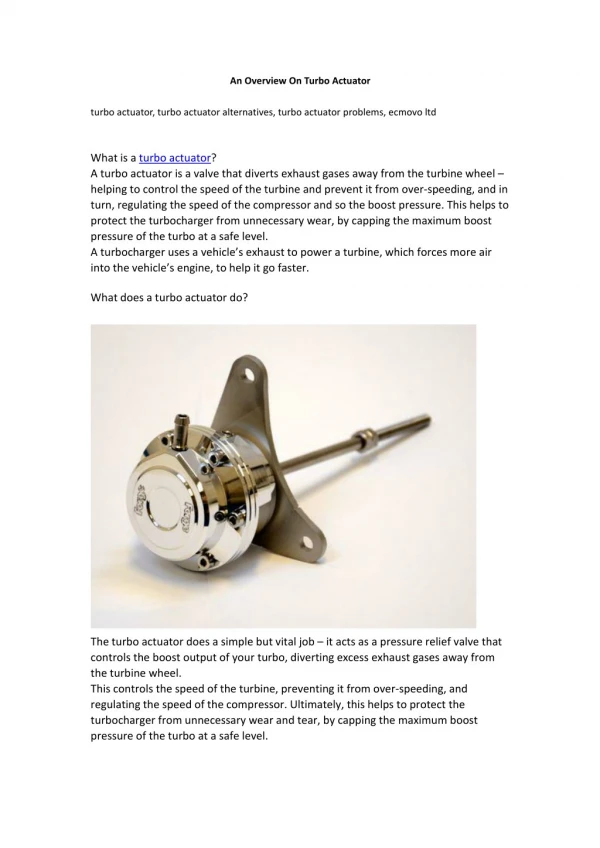
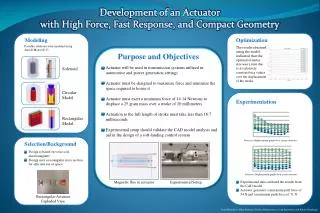
Explore the modeling and optimization of a high-force, fast-response actuator for automotive and power generation systems. The actuator, utilizing Ansoft Maxwell 13, achieves a compact design with optimal force exertion. Experimentation validates the CAD model for further refinement. Team members: Mina Almasry, Kirolos Athanassious, Cody Bannister, Kaiser Dandangi.

E N D
Development of an Actuator with High Force, Fast Response, and Compact Geometry Modeling Optimization Possible solutions were modeled using Ansoft Maxwell 13 The results obtained using the model indicated that the optimal orientor size was 2 mm due to its relatively constant force values over the displacement of the stroke Purpose and Objectives Solenoid Circular Model Rectangular Model Actuator will be used in transmission systems utilized in automotive and power generation settings Actuator must be designed to maximize force and minimize the space required to house it Actuator must exert a minimum force of 14.14 Newtons to displace a 25 gram mass over a stroke of 20 millimeters Actuation to the full length of stroke must take less than 16.7 milliseconds Experimental setup should validate the CAD model analysis and aid in the design of a soft-landing control system Experimentation Force vs. Displacement graph for a 15 mm orientor Selection/Background Design is based on voice-coil electromagnets Design uses a rectangular cross section for efficient use of space • Force vs. Displacement graph for a 2 mm orientor Experimental Setup Magnetic flux in actuator Experimental data validated the results from the CAD model Actuator generates a maximum pull force of 34 N and a maximum push force of 31 N Rectangular Actuator Exploded View Team Members: Mina Almasry, Kirolos Athanassious, Cody Bannister, and Kaiser Dandangi