Download
1 / 17
190 likes | 516 Views
A high force low area MEMS thermal actuator. 2004.10.9 윤용진. Abstract. This paper presents a new type of mems(micro-electro-mechanical systems)actuator consisting of an array of in-plane micro-fabricated thermal buckle-beam actuators

E N D
A high force low area MEMSthermal actuator 2004.10.9 윤용진
Abstract • This paper presents a new type of mems(micro-electro-mechanical systems)actuator consisting of an array of in-plane micro-fabricated thermal buckle-beam actuators • The technology used in MEMS actuators is typically magnetic,electrostatic or thermal. • Magnetic actuators may require special materials in the fabrication process • Electrostatic actuators typically require high voltages, large chip areas and produce very lowforces • Thermal actuators typically generate on the order of a few micro-Newtons each but can be combined for larger forces by linking with small tendons. • A disadvantage of this type of actuator is that it moves in an arc where most desired movements are linear. Also, when combined in an array, the linking tendons consume much ofthe energy in bending them. Also, arrays of these can still occupy a fairly large chip area.
Abstract • The electro-thermal actuator described here resembles a chevron where an array of buckle-beams are packed close together and link two common anchored arms with a movable third arm. • Arrays can be made within a single released micromachined layer and generate many mN of force. Additional actuators can be arrayed with no coupling penalty and occupy much less area that an equivalent pseudo-bimorph actuator. • Preliminary tests indicate that a 450 x 120 μm array consumes 240 mW ofpower, deflection up to 14 μm and can produce many milli-newtons. Achip of actuator geometry variations and different applications has been fabricated and tested.
Introduction • The desired attributes of an internal actuator are small chip real estate, large deflection (>lO μm) and an electrical requirement compatible with today’s CMOS circuitry. • MEMS actuators are typically used for either one-time deployment of structures for automatic assembly, an in-use adjustment such as focusing ortweaking an optical parameter or constant periodic actuation as in the case of micro-optic scanners. • Electrostatic actuators rely on the attractive forces between oppositely charged conductors in close proximity. Magnetic actuation uses the force of attraction or repulsion between a magnetic field produced by an electric current and a magnetic material or other electromagnet. • Electro-thermal actuators rely on the joule heating and resulting small mechanical expansion of a conductor when a current is passed through it.
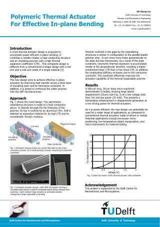
Introduction • Conversely, employing the thermal actuator array proposed by Reid [2], one can achieve about 450 μN per square mm of MEMS chip area. • The electrical power required is 3.87 mW perμN. These actuators depend on the differential thermal expansion of two polysilicon arms to produce a pseudobimorph that deflects inan arc. For an array, these devices may be coupled to a beam through bending yokes. • The actuator array presented here consists of only one thermal expansion beam per actuator and can produce about 3700 μN per square mm and 1.53 mW per μN. As structures become more complicated, especially in the case of free-space optical devices [3] • the one-time deployment required for assembly becomes more important and reliant on high-force, low-area actuators. Many of the deployment actuators today are of the comb drive type and typically occupy many times the area of the device they are deploying.
Device fabrication • The tested actuators were fabricated using the Multi-User MEMS Processes (MUMPs) [4]. • MUMPs is a surface micromachining process employing a substrate, an insulating nitride layer and three structural polysilicon layers separated by two sacrificial oxide layers as shown in Fig. 1 Figure 1. Cross-section view of the MUMPs fabrication process showing three polysilicon layers with a single anchor point. • The second and third polysilicon layers (Poly1 and Poly2) are both releasable to act as movable structures. A 0.5 μm gold layer can be pattem-deposited on the Poly2 layer for optical reflection or increased conductivity. • The final step performed is an HF etch of the intervening sacrificial oxide layers and subsequent drying.
Actuator design • a voltage is applied between the mechanical anchors, ohmic heating of the two half-beams causes them to expand and ultimately buckle. • The resistivity of polysilicon allows the actuator to operate at voltages and currents compatible with standard integrated circuitry (CMOS). • The beam is normally designed with a pre-bend angle a so buckling will have an affinity to move in-plane Figure 2. Single buckle-beam actuator. The applied voltage causes ohmic heating and expansion between the two fixed anchors, buckling the beam at the midpoint. The actuator displacement d is given by d = [ L2 + 2 ( L ) L' - Lcos(a)2]1/2 - Lsin(a)
Actuator design • Arrays of buckle-beam devices can be easily designed by arranging them in a pattern resembling a chevron as shown in Fig. 3. • A center beam isadded to stiffen the midpoint and allow mechanical coupling of the individual beams as well as providing a method of transmitting the linear force to another device. • There is no theoretical limit to the number of beams added as long as the device and conductors can handle the current and heat, • the beams can lose heat rapidly and there is no cross coupling of heat from one beam to another. • Most of the actuator arrays explored in this paper consist of pairs of 218μm half-beams in varying number and thickness. Figure 3. An array of four buckle-beam actuators with the addition of a coupling beam. The output force is linear – four times that of a single actuator
Actuator design • If more than one actuator array is connected (mechanically and electrically) to a single micro-structure, care must be taken to eliminate any common mode currents that arise when the actuators are excited differently • Fig.4 shows an alternative method of lectrical connection to the buckle-beam array that can help eliminate this problem. • The current in Fig.3 passes from one anchor to the other, placing the centercoupling beam at the half-resistanceholtagk point. • The current shown in Fig. 4 is fed from both anchors toward the coupling beam, which is at ground or a common mode potential • Figure 4. Alternative connection methods to minimize cross currents. If more than one actuator array is connected to a microstructure, the common-mode current must be minimized or damage could result.
Actuator design • This alternate connection could also be used to cause unequal currents to flow in both halves of the array, moving the center coupling beam a small distance either way and orthogonal to the primary displacement direction. • This action is presently being explored in an application where the smaller displacement can be used to accurately position an external structure clamped by the larger displacement.
Force and deflection measurement • Figure 5. CAD image of a typical chevron actuator array. Note the capture bearings used to prevent the buckle-beams from deflecting out-of-plane. Figure 6. Cross-section view of the actuator array of Fig. 5.Note the dimple bearing used to reduce stiction.
Force and deflection measurement • The actuator is deflected about 7 μm. a probe is shown shortening the 130 μm force beam to 60 μm. • By measuring the deflection of the bending-beam, the applied force can be computed. Note that the applied force is not the same as the total force capability of the actuator. Figure 7. Photomicrograph of a chevron actuator array. The probe at the bottom is used to shorten the force-measuring beam to 60 pm For small deflections of the force beam, the applied force is calculated F = Etdw3/4 l3 where F = applied force ,E = Young’s modulus - 160 Gpa [7] t = beam thickness in μm , w = beam width in μm l =beam length in μm
Test results • A graph of actuator deflection for various pre-bend angles is shown in Fig. 8 • The data was taken from a number of 2 μm thick structures at two different applied forces by selecting force beam lengths of 130 and 60 μm. • It can be seen (and predicted) that actuators with a small pre-bend angle (<0.5 degrees) exhibited little or no deflection and hence little output force. • For very small pre-bend angles, the actuator sometimes refused to move in-plane and, instead, buckled out-of-plane. • Predictably, with larger pre-bend angles, the deflection was reduced but the available force increased. Fig. 8 also indicates that, for a 60 μm force beam, the optimal pre-bend is around 1degree for maximum deflection. Figure 8. Deflection distance vs. pre-bend angle results for 2.0 μm thick polysilicon actuators. Two different forcemeasuring beam lengths were used.
Test results • Fig. 9 is a graph of deflection for a series of 2 μm actuators with various pre-bend and excitation voltages. • It indicates that the actuators exhibit a linear response when the excitation is above 2 volts. The slope of the curves indicates the higher the pre-bend angle, the lower the deflection. • Deflection response was measured in all actuators to be around 2KHz. Figure 9. Actuator deflection vs.excitation voltage. All actuators appear to be linear for excitations greater than 2 volts. The slope is pre-bend angle dependent.
Conclusion • These actuators can be used almost anywhere MEMS linear motion is required. • They produce high force though consume considerable power. The small deflection (~10 μm) can be extended through leverage, gearing or clutcWfriction drive. • Using the technique described here, a buckle-beam actuator array consisting of 48 two pm thick beams would have an output force of around 240 pN and occupy an area of 65,OO sq. μm. This same force would require an array of pseudo bi-morph devices occupying 533,000 sq. μm of chip real estate or 12,000,000 sq. μm for an electrostatic actuator array. • Future work will consist of exploring other geometry variations of these actuators such as longer beam lengths, beam-to-beam spacing and methods to avoid out-of-plane buckling. • Applications will include deployment systems for optical devices, rotary motion, mirror scanners and other display devices.
Application • Figure 10. Photomicrograph of a thermally actuated gear motor. The actuators are connected in a common mode configuration and excited with two sources in phase quadrature that causes the drive gear to move in a circular pattern.