Download
1 / 33
541 likes | 1.5k Views
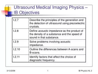
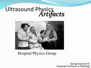
Ultrasound Physics. Artifacts. Hospital Physics Group. George David, M.S. Associate Professor of Radiology. Artifacts. Assumptions can cause artifacts when assumed conditions are not true sound travels at 1540 m/s sound travels in a straight line

E N D
Ultrasound Physics Artifacts Hospital Physics Group George David, M.S. Associate Professor of Radiology
Artifacts • Assumptions can cause artifacts when assumed conditions are not true • sound travels at 1540 m/s • sound travels in a straight line • All sound attenuation exactly0.5 dB/cm/MHz
Distance from Transducer • Echo positioning on image • distance from transducer calculated from assumed speed of sound • can place reflector too close to or too far from transducer • can alter size or shape of reflector V = 1380 m/s X Actual Object Position Position of Object on Image X V = 1540 m/s
Attenuation • For all scanning your scanner assumes • soft tissue attenuation • .5 dB/cm per MHz • Your scanner’s action • compensate for assumedattenuation • allow operator fine tuning • TGC
Shadowing • Clinical Manifestation • reduction in imaged reflector amplitude • Cause • object between this reflector & transducer attenuates ultrasound more than assumed • assumed compensation not enough to provide proper signal amplitude • intensity under-compensated • Opposite of Enhancement Attenuates more than .5 dB/cm/MHz Shadowed Reflector
Shadowing Attenuates more than .5 dB/cm/MHz Shadowed Reflector http://raddi.uah.ualberta.ca/~hennig/teach/cases/artifact/noframe/imag2-f2.htm
Enhancement • Clinical Manifestation • increase in imaged reflector amplitude • Cause • object between reflector & transducer attenuates ultrasound less than assumed • assumed compensation more than needed to provide proper signal amplitude • intensity over-compensated • Opposite of Shadowing Attenuates less .5 dB/cm/MHz Enhanced reflector
Enhancement Attenuates less .5 dB/cm/MHz Enhanced reflector http://raddi.uah.ualberta.ca/~hennig/teach/cases/artifact/noframe/imag6-f1.htm
Actual Object Position Position of Object on Image X Refraction Artifact • refraction alters beam direction • direction of sound travel assumed to be direction sound transmitted X Refraction
Refraction Artifact • refraction alters beam direction • scanner places dot in wrong location along line of assumed beam direction • can alter reflector shape
Lobe Artifacts • Side Lobes • beams propagating from a single element transducer in directions different from primary beam • reflections from objects here will be placed on main sound transmission line • Grating Lobes • same as above except for transducer arrays X
Range Ambiguity • Reflection from 1st pulse reaches transducer after 2nd pulse emitted • scanner assumes this is reflection from 2nd pulse • places echo too close & in wrong direction 1 2
Scanner Assumptions Multipath Artifact Actual Object Position Position of Object on Image X X
Multiple Reflection Scenario • reflection from reflector “B” splits at “A” • some intensity re-reflected toward “B” • Result • later false echoes heard • scanner places dots behind reflector “B” 2 3 1 A B real 1 2 false 3
Real Mirror Artifacts • Reverberation (multiple echo) artifact • “comet tail” effect is 1 example • can have dozens of multiple reflections between • transducer & reflector • 2 reflectors • Mirror Image • common around diaphragm& pleura
Artifacts http://raddi.uah.ualberta.ca/~hennig/teach/cases/artifact/noframe/imag1-f1.htm Caused by Shotgun Pellets
Real Mirror Multiple Reflection Scenario http://raddi.uah.ualberta.ca/~hennig/teach/cases/artifact/noframe/imag5-f2.htm
Resolution Artifacts • Axial and Lateral Resolution Limitations • results in failure to resolve 2 adjacent structures as separate • minimum image size equal to resolution in each direction
Section Thickness Artifact • anatomy may not be uniform over its thickness • universal problem of imaging 3D anatomy • in CT & MRI this is known as partial volume effect Thickness
Constructive Interference • 2 echoes received at same time • in phase • Result • higher intensity + =
Destructive Interference • 2 echoes received at same time • Exactly 180o out of phase • Result • flat (zero) wave - =
Acoustic Speckle • texture seen on image may not correspond to tissue texture • Results from interference effects between multiple reflectors received simultaneously which can • add together • constructive interference • subtract from one another • destructive interference
Mirror Image & Doppler • Analogous to mirror image artifact discussed previously • mirrored structures can include mirrored vessel • duplicate image visible on opposite side of strong reflector • example: bone • Doppler data also duplicated • flow & spectrum copied from original vessel
Spectral Duplication • mirror image of Doppler spectrum appears on opposite side of baseline • causes • electronic duplication caused by receiver gain set too high • overloads receiver • True sensing caused by too large Doppler angle • beam covers flow in both directions Blood flows toward transducer Blood flows away from transducer
Aliasing • Results in detection of improper flow direction • occurs because sampling rate too slow • Similar to wagon wheels rotating backwards in movies
Aliasing Sufficient Sampling Insufficient Sampling
Aliasing • Which way is this shape turning? OR #1 #2 #3
Aliasing Did the shape turn 1/4 turn right or 3/4 turn left? 1 1/4 turn right? #1 #2 #3
Aliasing Does it help to sample more often? #2 #1 #1A #2A #3A #3
Aliasing • Maximum detectable Doppler shift equals half the pulse repetition frequency • Sampling rate • Same as pulse repetition frequency • Must be at least twice highest frequency to be sensed • Aliasing occurs when Doppler shift exceeds 0.5 * PRF
Coping with Aliasing • decrease transducer frequency • reduces Doppler shift • shift proportional to operating frequency • increase pulse repetition frequency • decreases maximum imaging depth • increases likelihood of range ambiguity for pulsed instruments 77 X fD (kHz) v (cm/s) = -------------------------- fo (MHz) X cosq
q Coping with Aliasing • increase Doppler angle • Reduces relative flow rate between blood & transducer • Reduces Doppler shift sensed by scanner 77 X fD (kHz) v (cm/s) = -------------------------- fo (MHz) X cosq
Coping with Aliasing:Baseline Shifting • operator instructs scanner to assume that aliasing is occurring • scanner does calculations based on operator’s assumption • scanner has no way of determining where in image aliasing occurs Yes No