Download
1 / 72
1.39k likes | 4.15k Views
Ultrasound Physics. Have no fear Presentation by Alexis Palley MD Department of Emergency Medicine Cooper University Hospital . “How does it do that?” Lecture Objectives:. Review basic physics vocabulary Explain the principles of sound waves

E N D
Ultrasound Physics Have no fear Presentation by Alexis Palley MD Department of Emergency Medicine Cooper University Hospital
“How does it do that?” Lecture Objectives: • Review basic physics vocabulary • Explain the principles of sound waves • Use ultrasound physics to explain how images are produced • Teach how to use these principles to help your diagnostic abilities
Basics • Sound is energy traveling though matter as a wave • The wave travels by compressing and rarefacting matter • Depending on the matter- the wave will travel at different velocities or directions • U/S probes emit and receive the energy as waves to form pictures
Cycle Cycle • 1 Cycle = 1 repetitive periodic oscillation VOCAB
Frequency • # of cycles per second • Measured in Hertz (Hz) -Human Hearing 20 - 20,000 Hz -Ultrasound > 20,000 Hz -Diagnostic Ultrasound 2.5 to 10 MHz (this is what we use!) VOCAB
1 second = 1 Hertz frequency 1 cycle in 1 second = 1Hz VOCAB
High Frequency • High frequency (5-10 MHz) greater resolution less penetration • Shallow structures vascular, abscess, t/v gyn, testicular
Low Frequency • Low frequency (2-3.5 MHz) greater penetration less resolution • Deep structures Aorta, t/a gyn, card, gb, renal
Wavelength • The length of one complete cycle • A measurable distance VOCAB
Wavelength Wavelength VOCAB
Amplitude Amplitude • The degree of variance from the norm VOCAB
Producing an image • Probe emits a sound wave pulse-measures the time from emission to return of the echo • Wave travels by displacing matter, expanding and compressing adjacent tissues • It generates an ultrasonic wave that is propagated, impeded, reflected, refracted, or attenuated by the tissues it encounters
Producing an image • Important concepts in production of an U/S image: • Propagation velocity • Acoustic impedance • Reflection • Refraction • Attenuation
Propagation Velocity • Sound is energy transmitted through a medium- • Each medium has a constant velocity of sound(c) • Tissue’s resistance to compression • density or stiffness • Product of frequency (f) and wavelength (λ) c=fλ • Frequency and Wavelength therefore are directly proportional- if the frequency increases the wavelength must decrease.
Propagation Velocity • Propagation velocity Increased by increasing stiffness Reduced by increasing density • Bone: 4,080 m/sec • Air: 330 m/sec • Soft Tissue Average: 1,540 m/sec
Impedance • Acoustic impedance (z) of a material is the product of its density and propagation velocity Z= pc • Differences in acoustic impedance create reflective interfaces that echo the u/s waves back at the probe • Impedance mismatch = ΔZ
Acoustic Impedance • Homogeneous mediums reflect no sound • acoustic interfaces create visual boundaries between different tissues. • Bone/tissue or air/tissue interfaces with large Δz values reflect almost all the sound • Muscle/fat interfaces with smaller Δz values reflect only part of the energy
Refraction • A change in direction of the sound wave as it passes from one tissue to a tissue of higher or lower sound velocity • U/S scanners assume that an echo returns along a straight path • Distorts depth reading by the probe • Minimize refraction by scanning perpendicular to the interface that is causing the refraction
Reflection • The production of echoes at reflecting interfaces between tissues of differing physical properties. • Specular - large smooth surfaces • Diffuse – small interfaces or nooks and crannies
Specular Reflection • Large smooth interfaces (e.g. diaphragm, bladder wall) reflect sound like a mirror • Only the echoes returning to the machine are displayed • Specular reflectors will return echoes to the machine only if the sound beam is perpendicular to the interface
Diffuse Reflector • Most echoes that are imaged arise from small interfaces within solid organs • These interfaces may be smaller than the wavelength of the sound • The echoes produced scatter in all directions • These echoes form the characteristic pattern of solid organs and other tissues
Reflectors Specular Diffuse
Attenuation • The intensity of sound waves diminish as they travel through a medium • In ideal systems sound pressure (amplitude) is only reduced by the spreading of waves • In real systems some waves are scattered and others are absorbed, or reflected • This decrease in intensity (loss of amplitude) is called attenuation.
Ultrasound scanners • Anatomy of a scanner: • Transmitter • Transducer • Receiver • Processor • Display • Storage
Transmitter • a crystal makes energy into sound waves and then receives sound waves and converts to energy • This is the Piezoelectric effect • u/s machines use time elapsed with a presumed velocity (1,540 m/s) to calculate depth of tissue interface • Image accuracy is therefore dependent on accuracy of the presumed velocity.
Transducers • Continuous mode • continuous alternating current • doppler or theraputic u/s • 2 crystals –1 talks, 1 listens • Pulsed mode • Diagnostic u/s • Crystal talks and then listens
Receiver • Sound waves hit and make voltage across the crystal- • The receiver detects and amplifies these voltages • Compensates for attenuation
TGC (time gain compensation) Manual control Selective enhancement or suppression of sectors of the image enhance deep and suppress superficial *blinders Gain Manual control Affects all parts of the image equally Seen as a change in “brightness” of the images on the entire screen *glasses Signal Amplification
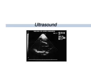
Displays • B-mode • Real time gray scale, 2D • Flip book- 15-60 images per second • M-mode • Echo amplitude and position of moving targets • Valves, vessels, chambers
Image properties • Echogenicity- amount of energy reflected back from tissue interface • Hyperechoic - greatest intensity - white • Anechoic - no signal - black • Hypoechoic – Intermediate - shades of gray
Anechoic Hyperechoic Hypoechoic
Image Resolution • Image quality is dependent on • Axial Resolution • Lateral Resolution • Focal Zone • Probe Selection • Frequency Selection • Recognition of Artifacts
Axial Resolution • Ability to differentiate two objects along the long axis of the ultrasound beam • Determined by the pulse length • Product of wavelength λ and # of cycles in pulse • Decreases as frequency f increases • Higher frequencies produce better resolution
5 MHz transducer Wavelength 0.308mm Pulse of 3 cycles Pulse length approximately 1mm Maximum resolution distance of two objects = 1 mm 10 MHz transducer Wavelength 0.15mm Pulse of 3 cycles Pulse length approximately 0.5mm Maximum resolution distance of two objects = 0.5mm Axial Resolution
Axial Resolution screen body
Lateral Resolution • The ultrasound beam is made up of multiple individual beams • The individual beams are fused to appear as one beam • The distances between the single beams determines the lateral resolution
Lateral resolution • Ability to differentiate objects along an axis perpendicular to the ultrasound beam • Dependent on the width of the ultrasound beam, which can be controlled by focusing the beam • Dependent on the distance between the objects
Lateral Resolution screen body
Objects within the focal zone Objects outside of focal zone Focal Zone Focal zone Focal zone
Linear Array Curved Array Probe options
Ultrasound Artifacts • Can be falsely interpreted as real pathology • May obscure pathology • Important to understand and appreciate
Ultrasound Artifacts • Acoustic enhancement • Acoustic shadowing • Lateral cystic shadowing (edge artifact) • Wide beam artifact • Side lobe artifact • Reverberation artifact • Gain artifact • Contact artifact
Acoustic Enhancement • Opposite of acoustic shadowing • Better ultrasound transmission allows enhancement of the ultrasound signal distal to that region