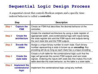
Sequential Circuit Design: State Minimization and Encoding Techniques
This lecture focuses on the important concepts of state minimization and state encoding in the design of sequential circuits. It presents techniques for synthesizing sequential networks by minimizing the number of states and efficiently encoding them. Essential examples illustrate the process of merging equivalent states and representational strategies using State Transition Tables (STT) and Primary Output Tables (POT). Students are encouraged to apply learned techniques to exercises and referenced readings to delve deeper into sequential logic minimization algorithms.

Sequential Circuit Design: State Minimization and Encoding Techniques
E N D
Presentation Transcript
Lecture 7.2 Paolo PRINETTO Politecnico di Torino (Italy)University of Illinois at Chicago, IL (USA) Paolo.Prinetto@polito.it Prinetto@uic.edu www.testgroup.polito.it Logic level sequential design (2)
Goal • This lecture is the latter part of a group of 2 lectures (split just for sake of manageability) aiming at presenting the sequence of steps to be performed in the manual synthesis of sequential networks.
Prerequisites • Lecture 7.1
Homework • Students are invited to try to solve the proposed exercises by themselves, before looking at the proposed solutions
Further readings • See Lecture 7.1
Further readings (cont’d) • In particular, students interested in sequentiallogic minimization algorithms are invited to refer to • G. De Micheli: “Synthesis and Optimization of digital circuits,”McGraw-Hill, Inc, New York, NJ, USA, 1994, (chapters 9, pp. 441-503)
Outline • State minimization • State encoding • Library binding
State minimization Stateminimization system RT logic device Aims at minimizing the global number of states behavior structure physical
Equivalent states • Two states are equivalent iff for every possible input combination: • The corresponding POs are the same • The corresponding next states are equal or equivalent
Examples • A B A,0 B,0 0 1 1 0 C D
Examples • If (C D) and (E F) then A B A,0 B,0 1 1 0 0 C E F D
Note • State minimization algorithms are outside the scope of the course.
State minimization • If states A and B proved to be equivalent, you can simplify the STG by merging them. • This practically means, either: • Deleting either A or B (let’s assume, for instance, of deleting B) • Redirecting to A all the edges that leaded to B or • Merging them into a new state • Erasing redundant edges.
Example Z X Y 1 0 • A B. 1 0 A,0 B,0 0 1 1 0 C D
Deleting • Let’s delete B Z X Y 1 0 1 0 A,0 B,0 0 1 1 0 C D
Deleting • Let’s delete B Z X Y 1 0 1 0 A,0 1 0 C D
Deleting • Let’s redirect the edges Z X Y 1 1 0 0 A,0 1 0 C D
Deleting • State Y can be simplified Z X Y - 1 0 A,0 1 0 C D
Merging • Let’s merge A and B Z X Y 1 0 1 0 A,0 B,0 0 1 1 0 C D
Merging • Let’s merge A and B Z X Y 1 0 1 0 A,0 B,0 0 1 1 0 C D
Merging Z X Y 1 0 1 0 A_B, 0 1 0 C D
Merging • Let’s erase redundant edges Z X Y 1 - 0 A_B, 0 1 0 C D
Tabular representation • At this stage of the synthesis process, it’s convenient translating the STG into an equivalent tabular representation, based on two tables: • the State Transition Table (STT) • the Primary Output Table (POT). • Both tables have: • as many rows as the states are • 2# PI columns.
PI j PS i NS State Transition Table The cell (i, j) stores the value of the next state of the state i when the PI's get the value j.
Primary Output Table The cell (i, j) stores the value of the PO’s when the machine is the state i and the PI's get the value j. PI j PS i PO
POT of Moore machines PI PS PO
POT of Mealy machines PI PS PO
010 Solution reset 1 0 R,0 0,0 0 1 1 0 1 01,0 010,1 0
010 reset 1 0 A,0 B,0 A,0 B,0 0 1 0 1 1 C,0 C,0 D,1 D,1 0 Solution reset 1 0 R,0 0,0 0 1 1 0 1 01,0 010,1 0
010 x reset 1 0 PS A,0 B,0 A,0 B,0 0 1 0 1 1 C,0 C,0 D,1 D,1 0 NS U Solution • 0 1 • A • B • C • D
010 x reset 1 0 PS A,0 B,0 A,0 B,0 0 1 0 1 1 C,0 C,0 D,1 D,1 0 NS U Solution • 0 1 • A B A 0 • B • C • D
010 x reset 1 0 PS A,0 B,0 A,0 B,0 0 1 0 1 1 C,0 C,0 D,1 D,1 0 NS U Solution • 0 1 • A B A 0 • B B C 0 • C D A 0 • D B A 1
Outline • State minimization • State encoding • Library binding
State encoding State encoding system RT logic device Aims at determining the binary representation of the states, i.e., at assigning each state a binary value to be stored in the state register behavior structure physical
0 1 A B A 0 B B D 0 C B A 1 D C A 0 State encoding STT x presentstates system RT logic device nextstates U behavior structure physical
0 0 1 1 A 00 01 B 00 A 0 0 B 01 01 B D 10 0 0 11 C B 01 A 00 1 1 D 10 11 C 00 A 0 0 State encoding STT x presentstates system RT logic device x y[1:0] nextstates U behavior structure physical U Y[1:0]
0 1 00 01 00 0 01 01 10 0 11 01 00 1 10 11 00 0 State encoding STT system RT logic device x y[1:0] behavior structure physical U Y[1:0]
0 1 00 01 00 0 01 01 10 0 11 01 00 1 10 11 00 0 State encoding STT Y[1] = x’y[1]y[0]’ + xy[1]’y[0] Y[0] = x’ U = y[1]y[0] system RT logic device x y[1:0] behavior structure physical U Y[1:0]
State encoding STT State transition function Y[1] = x’y[1]y[0]’ + xy[1]’y[0] Y[0] = x’ U = y[1]y[0] system RT logic device Output function behavior structure physical
State variables • The minimum number N of required state variables (i.e., of flip-flops) is always: • N = log2 # states
Assignment choices • The total number SA of nonequivalent state assignments with N states and Q state variables is given by: • (2Q - 1)!(2Q - N)! Q! SA =
State encoding strategies • No practical way is known to find the state assignment providing a minimum cost implementation. • The most widely adopted strategies are the following: • random • one-hot • heuristic-based.
Random encoding • Encoding is performed in a random way • It’s the most widely used in manual design.
010 x PS NS U Solution (random) • 0 1 • A B A 0 • B B C 0 • C D A 0 • D B A 1
010 x PS NS U Solution (random) • 0 1 • A B A 0 • B B C 0 • C D A 0 • D B A 1 state encoding A 00 B 01 C 10 D 11
One-hot encoding • It uses one flip-flop per state, instead of the minimum # log2 # states • For each state just the corresponding state variable is set to 1, while all the other ones are set to 0.
010 x PS NS U Solution (one-hot) • 0 1 • A B A 0 • B B C 0 • C D A 0 • D B A 1
010 x PS state encoding A 0001 B 0010 C 0100 D 1000 NS U Solution (one-hot) • 0 1 • A B A 0 • B B C 0 • C D A 0 • D B A 1
Heuristic-basedencoding • Encoding is performed resorting to minimization algorithms, tailored to the minimization of some parameters, like area, delay, # of state variables, ...
Note • State assignement algorithms are outside the scope of the course.