Download
1 / 35
350 likes | 360 Views
Explore the technology and advancements in fuel cell vehicles, including hydrogen separation, powertrain layout, high-pressure storage tanks, and refueling options.

E N D
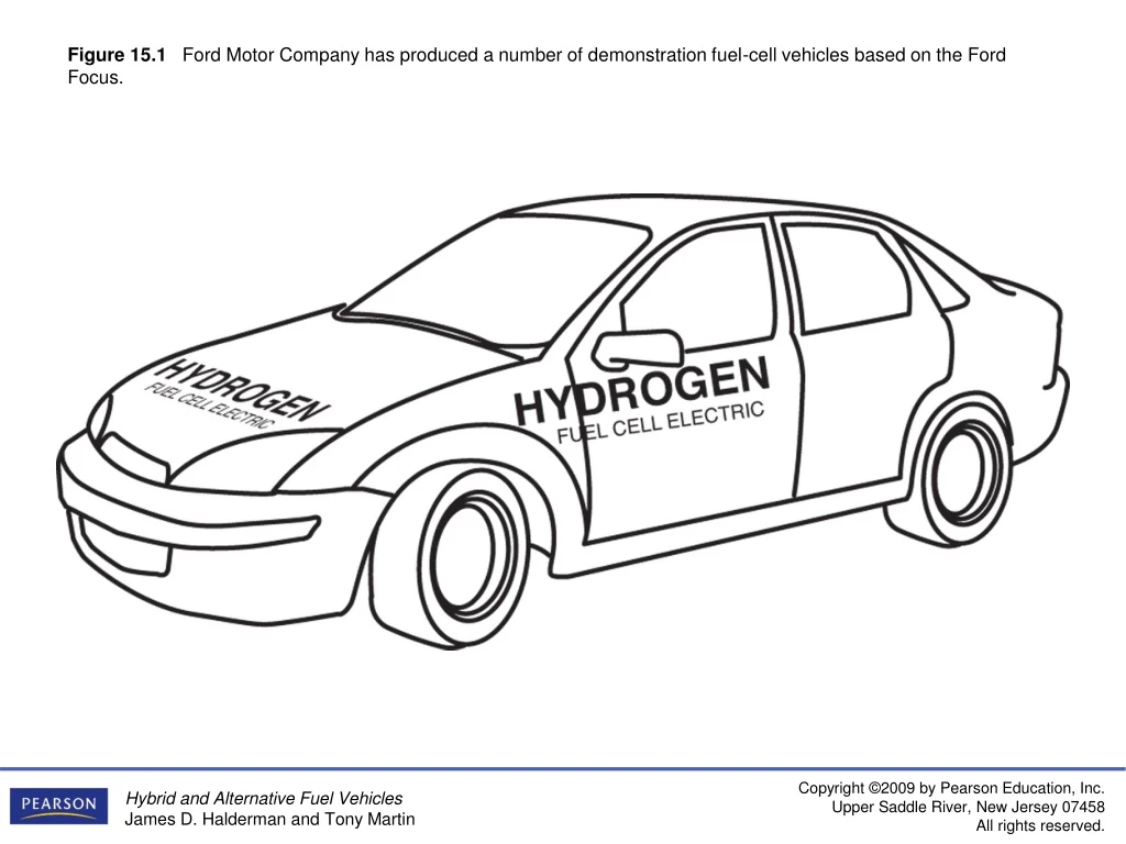
Figure 15.1 Ford Motor Company has produced a number of demonstration fuel-cell vehicles based on the Ford Focus.
Figure 15.2 Hydrogen does not exist by itself in nature. Energy must be expended to separate it from other,more complex materials. (Courtesy of University of Toyota and Toyota Motor Sales, U.S.A., Inc.)
Figure 15.3 The Mercedes-Benz B-Class fuel-cell car was introduced in 2005.
Figure 15.4 The Toyota FCHV is based on the Highlander platform and uses much of Toyota’s Hybrid Synergy Drive (HSD) technology in its design.
Figure 15.5 The polymer electrolyte membrane only allows H+ ions (protons) to pass through it.This means that electrons must follow the external circuit and pass through the load to perform work. (Courtesy of Universityof Toyota and Toyota Motor Sales, U.S.A., Inc.)
Figure 15.6 A fuel-cell stack is made up of hundreds of individual cells connected in series.
Figure 15.7 A direct methanol fuel cell uses a methanol/water solution for fuel instead of hydrogen gas.
Figure 15.8 A direct methanol fuel cell can be refueled similar to a gasoline-powered vehicle.
Figure 15.9 Power train layout in a Honda FCX fuel-cell vehicle. Note the use of a humidifier behind the fuel-cell stack to maintain moisture levels in the membrane electrode assemblies.
Figure 15.10 The Honda FCX uses one large radiator for cooling the fuel cell, and two smaller ones on either side for cooling drive train components.
Figure 15.11 Space is limited at the front of the Toyota FCHV engine compartment, so an auxiliary heat exchanger is located under the vehicle to help cool the fuel-cell stack.
Figure 15.12 The secondary battery in a fuel-cell hybrid vehicle is made up of many individual cells connected in series, much like a fuel-cell stack. (Courtesy of University of Toyota and Toyota Motor Sales, U.S.A., Inc.)
Figure 15.13 The Honda ultracapacitor module and construction of the individual cells.
Figure 15.14 An ultracapacitor can be used in place of a high-voltage battery in a hybrid electric vehicle. This example is from the Honda FCX fuelcell hybrid vehicle.
Figure 15.15 Drive motors in fuel-cell hybrid vehicles often use stator assemblies similar to ones found in Toyota hybrid electric vehicles. The rotor turns inside the stator and has permanent magnets on its outer circumference.
Figure 15.16 The General Motors “Skateboard” concept uses a fuel-cell propulsion system with wheel motors at all four corners.
Figure 15.17 The electric drive motor and transaxle assembly from a Toyota FCHV. Note the three orange cables, indicating that this motor is powered by high-voltage three-phase alternating current. (Courtesy of University ofToyota and Toyota Motor Sales, U.S.A., Inc.)
Figure 15.18 The power control unit (PCU) on a Honda FCX fuel-cell hybrid vehicle is located under the hood.
Figure 15.19 Toyota’s FCHV uses a power control unit that directs electrical energy flow between the fuel cell, battery, and drive motor. (Courtesy of University of Toyota and Toyota Motor Sales, U.S.A., Inc.)
Figure 15.20 This GM fuel-cell vehicle uses compressed hydrogen in three high-pressure storage tanks.
Figure 15.21 The Toyota FCHV uses high-pressure storage tanks that are rated at 350 bar. This is the equivalent of 5,000 pounds per square inch. (Courtesy of University of Toyota and Toyota Motor Sales, U.S.A., Inc.)
Figure 15.22 The high-pressure fitting used to refuel a fuel-cell hybrid vehicle.
Figure 15.23 This connector is used while refueling the compressed hydrogen tanks on a Toyota FCHV.
Figure 15.24 GM’s Hydrogen3 has a range of 249 miles when using liquid hydrogen.
Figure 15.26 Carbon deposits, such as these, are created by incomplete combustion of a hydrocarbon fuel.
Figure 15.27 Both diesel and conventional gasoline engines create exhaust emissions due to high peak temperatures created in the combustion chamber. The lower combustion temperatures during HCCI operation result in high efficiency with reduced emissions.
Figure 15.28 A typical electric vehicle charging station on the campus of a college in Southern California.
Figure 15.29 A conductive-type charging connector. This type of battery charging connector is sometimes called a AVCON connector, named for the manufacturer.
Figure 15.30 An inductive-type electric vehicle battery charger connector. This type of connector fits into a charging slot in the vehicle, but does not make electrical contact.
Figure 15.31A The motor in a compact electric drag car. This 8-inch-diameter motor is controlled by an electronic controller that limits the voltage to 170 volts to prevent commutator flash-over yet provides up to 2,000 amperes. This results in an amazing 340,000 watts or 455 Hp.
Figure 15.31B The batteries used for the compact drag car include twenty 12-volt absorbed glass mat (AGM) batteries connected in series to provide 240 volts.
Figure 15.32 Wind power capacity by area. (Courtesy of U.S. Department of Energy)
Figure 15.33 A typical wind generator that is used to generate electricity.
Figure 15.34 The Hoover Dam in Nevada/Arizona is used to create electricity for use in the southwest United States.