Multiplexers and Demultiplexers in Logic Circuits
Explore the concepts of multiplexers and demultiplexers in logic circuits, their gate-level implementation, and application as general-purpose logic functions. Learn about cascading, truth table configurations, and how these components can be configured to perform various logic functions efficiently.

Multiplexers and Demultiplexers in Logic Circuits
E N D
Presentation Transcript
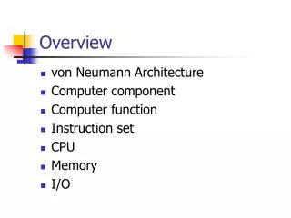
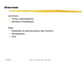
Overview • Last lecture • Timing; Hazards/glitches • Definition of Multiplexers • Today • Multiplexers as general-purpose logic functions • Demultiplexers • PLA’s CSE 370 – Winter 2002 - Hazards - 1
I1 I0 A Z0 0 0 00 0 1 00 1 0 10 1 1 01 0 0 01 0 1 11 1 0 11 1 1 1I1 I0 A Z0 0 0 00 0 1 00 1 0 10 1 1 01 0 0 01 0 1 11 1 0 11 1 1 1 A Z0 I01 I1 Multiplexers (aka selectors) • Multiplexers/selectors: general concept • 2n data inputs, n control inputs (called "selects"), 1 output • used to connect 2n points to a single point • control signal pattern forms binary index of input connected to output Z = A' I0 + A I1 A is control I0 , I1 are input Z is output functional form logical form two alternative forms for a 2:1 Mux truth table CSE 370 – Winter 2002 - Hazards - 2
I0I1I2I3I4I5I6I7 8:1mux Z I0I1I2I3 4:1mux Z I0I1 2:1mux Z A A B A B C Multiplexers/selectors (cont'd) • 2:1 mux: Z = A' I0 + A I1 • 4:1 mux: Z = A' B' I0 + A' B I1 + A B' I2 + A B I3 • 8:1 mux: Z = A' B' C' I0 + A' B' C I1 + A' B C' I2 + A' B C I3 + A B' C' I4 + A B' C I5 + A B C' I6 + A B C I7 • In general, Z = (mkIk) • in minterm shorthand form for a 2n:1 Mux n 2 -1 k=0 CSE 370 – Winter 2002 - Hazards - 3
Gate level implementation of muxes • 2:1 mux • 4:1 mux CSE 370 – Winter 2002 - Hazards - 4
I0I1I2I3 8:1mux 4:1mux Z 2:1mux I4I5I6I7 I0I1 8:1mux 2:1mux 4:1mux I2I3 2:1mux 4:1mux Z B C A I4I5 2:1mux I6I7 2:1mux A B C Cascading multiplexers • Large multiplexers can be implemented by cascading smaller ones alternativeimplementation control signals B and C simultaneously choose one of I0, I1, I2, I3 and one of I4, I5, I6, I7control signal A chooses which of theupper or lower mux's output to gate to Z CSE 370 – Winter 2002 - Hazards - 5
10100011 01234567 F 8:1 MUX S2 S1 S0 A B C Multiplexers as general-purpose logic • A 2n:1 multiplexer can implement any function of n variables • with the variables used as control inputs and • the data inputs tied to 0 or 1 • in essence, a lookup table • Example: • F(A,B,C) = m0 + m2 + m6 + m7 = A'B'C' + A'BC' + ABC' + ABC CSE 370 – Winter 2002 - Hazards - 6
10100011 01234567 A B C F0 0 0 10 0 1 00 1 0 10 1 1 01 0 0 01 0 1 01 1 0 11 1 1 1 C'C'01 C'C'01 0123 F 4:1 MUX 8:1 MUX S1 S0 A B S2 S1 S0 A B C Multiplexers as general-purpose logic (cont’d) • A 2n-1:1 multiplexer can implement any function of n variables • with n-1 variables used as control inputs and • the data inputs tied to the last variable or its complement • Example: • F(A,B,C) = m0 + m2 + m6 + m7 = A'B'C' + A'BC' + ABC' + ABC = A'B'(C') + A'B(C') + AB'(0) + AB(1) F CSE 370 – Winter 2002 - Hazards - 7
1D01D’DD’D’ 01234567 A 1 1 0 0 1 0 1 0 8:1 MUX D 0 1 1 0 1 1 0 1 S2 S1 S0 C B A B C Multiplexers as general-purpose logic (cont’d) • Generalization • Example: F(A,B,C,D) can be implemented by an 8:1 MUX I0 I1 . . . In-1 In F. . . . 0 0 011. . . . 1 0 101 0 In In' 1 four possible configurationsof truth table rows can be expressedas a function of In • n-1 mux control variables • single mux data variable choose A,B,C as control variablesmultiplexer implementation CSE 370 – Winter 2002 - Hazards - 8
Demultiplexers (aka decoders) • Decoders/demultiplexers: general concept • single data input, n control inputs, 2n outputs • control inputs (called “selects” (S)) represent binary index of output to which the input is connected • data input usually called “enable” (G) 1:2 Decoder: O0 = G S’ O1 = G S 3:8 Decoder: O0 = G S2’ S1’ S0’ O1 = G S2’ S1’ S0 O2 = G S2’ S1 S0’ O3 = G S2’ S1 S0 O4 = G S2 S1’ S0’ O5 = G S2 S1’ S0 O6 = G S2 S1 S0’ O7 = G S2 S1 S0 2:4 Decoder: O0 = G S1’ S0’ O1 = G S1’ S0 O2 = G S1 S0’ O3 = G S1 S0 CSE 370 – Winter 2002 - Hazards - 9
G \G O0 O0 S S O1 O1 G \G O0 O0 O1 O1 O2 O2 O3 O3 S1 S1 S0 S0 Gate level implementation of demultiplexers • 1:2 decoders • 2:4 decoders active-high enable active-low enable active-high enable active-low enable CSE 370 – Winter 2002 - Hazards - 10
01234567 A'B'C'A'B'CA'BC'A'BCAB'C'AB'CABC'ABC “1” 3:8 DEC S2 S1 S0 A B C Demultiplexers as general-purpose logic • A n:2n decoder can implement any function of n variables • with the variables used as control inputs • the enable inputs tied to 1 and • the appropriate minterms summed to form the function demultiplexer generates appropriate minterm based on control signals (it "decodes" control signals) CSE 370 – Winter 2002 - Hazards - 11
0 A'B'C'D'1 A'B'C'D2 A'B'CD'3 A'B'CD4 A'BC'D'5 A'BC'D6 A'BCD'7 A'BCD8 AB'C'D'9 AB'C'D10 AB'CD'11 AB'CD12 ABC'D'13 ABC'D14 ABCD'15 ABCD0 A'B'C'D'1 A'B'C'D2 A'B'CD'3 A'B'CD4 A'BC'D'5 A'BC'D6 A'BCD'7 A'BCD8 AB'C'D'9 AB'C'D10 AB'CD'11 AB'CD12 ABC'D'13 ABC'D14 ABCD'15 ABCD F1 4:16DEC Enable F2 F3 A B C D Demultiplexers as general-purpose logic (cont’d) • F1 = A' B C' D + A' B' C D + A B C D • F2 = A B C' D’ + A B C • F3 = (A' + B' + C' + D') CSE 370 – Winter 2002 - Hazards - 12
Cascading decoders • 5:32 decoder • 1x2:4 decoder • 4x3:8 decoders 0 A'B'C'D'E'1234567 012 A'BC'DE'34567 3:8 DEC 3:8 DEC S2 S1 S0 S2 S1 S0 0123 2:4 DEC F S1 S0 01234567 ABCDE 0 AB'C'D'E'1234567 AB'CDE A B 3:8 DEC 3:8 DEC S2 S1 S0 S2 S1 S0 C D C D E E CSE 370 – Winter 2002 - Hazards - 13
• • • inputs ORarray ANDarray productterms outputs • • • Programmable logic arrays • Pre-fabricated building block of many AND/OR gates • actually NOR or NAND • "personalized" by making or breaking connections among the gates • programmable array block diagram for sum of products form CSE 370 – Winter 2002 - Hazards - 14
product inputs outputs term A B C F0 F1 F2 F3AB 1 1 – 0 1 1 0B'C – 0 1 0 0 0 1AC' 1 – 0 0 1 0 0B'C' – 0 0 1 0 1 0A 1 – – 1 0 0 1 reuse of terms Enabling concept • Shared product terms among outputs F0 = A + B' C' F1 = A C' + A B F2 = B' C' + A B F3 = B' C + A example: input side: personality matrix 1 = uncomplemented in term 0 = complemented in term – = does not participate output side: 1 = term connected to output 0 = no connection to output CSE 370 – Winter 2002 - Hazards - 15
Before programming • All possible connections (2-level logic functions) are available before "programming" • in reality, all AND and OR gates are NANDs CSE 370 – Winter 2002 - Hazards - 16
B C A AB B'C AC' B'C' A F0 F1 F2 F3 After programming • Unwanted connections are "blown" • fuse (normally connected, break unwanted ones) • anti-fuse (normally disconnected, make wanted connections) CSE 370 – Winter 2002 - Hazards - 17
A B C D AB A'B' CD' C'D AB+A'B' CD'+C'D Alternate representation for high fan-in structures • Short-hand notation so we don't have to draw all the wires • signifies a connection is present and perpendicular signal is an input to gate notation for implementing F0 = A B + A' B' F1 = C D' + C' D CSE 370 – Winter 2002 - Hazards - 18
A B C A'B'C' A'B'C A'BC' A'BC AB'C' AB'C ABC' ABC A B C F1 F2 F3 F4 F5 F6 0 0 0 0 0 1 1 0 0 0 0 1 0 1 0 1 1 1 0 1 0 0 1 0 1 1 1 0 1 1 0 1 0 1 0 0 1 0 0 0 1 0 1 1 1 1 0 1 0 1 0 1 0 0 1 1 0 0 1 0 1 0 0 1 1 1 1 1 0 0 1 1 F1 F2 F3 F4 F5 F6 Programmable logic array example • Multiple functions of A, B, C • F1 = A B C • F2 = A + B + C • F3 = A' B' C' • F4 = A' + B' + C' • F5 = A xor B xor C • F6 = A xnor B xnor C full decoder as for memory address bits stored in memory CSE 370 – Winter 2002 - Hazards - 19