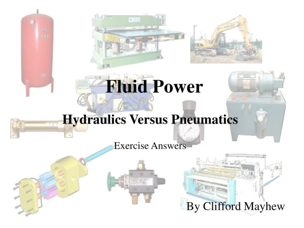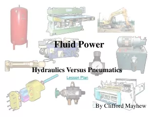
Fluid Power
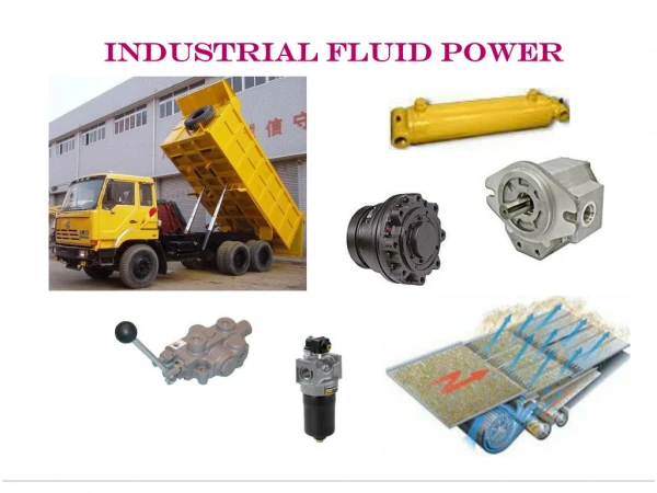
Fluid Power. Hydraulics Versus Pneumatics. Lesson Plan. By Clifford Mayhew. Pneumatic Control Is:. Hydraulic Control:. Pneumatic and Hydraulic Control Comparison. Is Infinitely Controllable Produces Extremely Large Forces Requires High Pressures Requires Heavy Duty Components. Clean

Fluid Power
E N D
Presentation Transcript
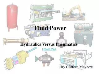
Fluid Power Hydraulics Versus Pneumatics Lesson Plan By Clifford Mayhew
Pneumatic Control Is: Hydraulic Control: Pneumatic and Hydraulic Control Comparison • Is Infinitely Controllable • Produces Extremely Large Forces • Requires High Pressures • Requires Heavy Duty Components • Clean • Fast • Intrinsically Safe • Overload Safe • Inexpensive for Individual Components
This injury is a result of placing the hand in front of a jet of leaking hydraulic fluid at around 180 Bar Pneumatic and Hydraulic Dangers The dangers of the use of compressed air include: • Air Embolism • Hose/Pipe Whipping • Noise • Crushing/Cutting The dangers of working with high pressure oil can be infinitely more drastic: • High Pressure Oil Injection • Oil Burns • Crushing/Cutting • Carcinogens
Compressor Pumps and Motors differ only by filling in the direction arrow or leaving it white. Hydraulic Pump Supply and Pilot arrows are also filled in or left white. Hydraulically Actuated and supplied 3/2 Pilot Spring Pneumatically Actuated and supplied 3/2 Pilot Spring Differences in Symbols Symbols Reminder
Differences in Symbols Hydraulic Double Acting Cylinder Pneumatic Double Acting Cylinder Hydraulic Filter Pneumatic Filter Remember however that the physical construction is completely different. For example, hydraulic filters can be either Suction Strainers (suction side of the pump), Pressure Filter (pressure side of the pump) or Return Filter (in the return to tank line). Each filter requires different properties. Cylinders and other actuators also differ with respect to supply and direction arrows. Many symbols do not change, for example the Filter symbol.
Differences in Symbols Hydraulic valves have a crossover to Tank. Pneumatic valves tend to have two Exhaust outlets to Atmosphere.
Differences in Medium Hydraulic Oil is Hygroscopic and can be easily Oxidised at high temperatures. Hydraulic Fluid is viscous and can be various types with varying Viscosities including: • Flame Retardant • Mineral Oil • Synthetic Oil • Water Glycol Hydraulic fluid can have many additives including: • Anti Oxidants • Lubricity Improvement • Anti Foaming Additive • Anti Wear Additives Air can hold Moisture which can turn into Condensation at the Dew Point. The pneumatic components must remove the Condensation from the air and provide Lubrication. Air is safe under a wide range of operating temperatures.
Differences in Principles and Properties Pneumatic systems rely on a supply of Compressed air flowing through Pipes to Actuators. The Force for work is produced due to the Pressure of the Air acting on the Area of the actuator. Air is Compressible. Gas laws such as Boyle’s and Charles’s Laws govern medium behaviour Actuator demand is measured in m3 per hour or operation Compressor output is measured in m3 per hour Free Air Delivery (FAD) Hydraulic systems rely on a supply of incompressible fluid flowing through Hoses to Actuators. The Force for work is produced due to the Pressure of the Oil acting on the Area of the actuator. Oil is considered Incompressible. Bernoulli’s and other Fluid Flow Laws govern medium behaviour Actuator demand is measured litres per minute for a specific speed Pump output is measured litres per minute Both Hydraulics and Pneumatics are described with Pascal’s Law and F=PA
Force Force Calculator Area Pressure Differences in Pressure and Force Pneumatic Pressures and Forces • Produced at 10Bar • Used at 0~6 Bar • Forces up to 5000Kg Hydraulic Pressures and Forces • Produced and used at 200~400Bar • Forces up to Thousands of tonnes
The hydraulic Power Pack contains the Pump, Tank (Reservoir), Filters and commonly a Relief Valve for protection of the system. The unit is usually local to the machine that is using it. Hydraulic pumps are usually Positive Displacement devices which means they displace all the oils they pump. The Pneumatic Compressor installation usually includes a Dryer and Receiver. The unit is usually remote from the machine that is using it. Differences in ConstructionProduction
Pneumatic valves and actuators are generally of light construction as they need to deal with pressure up to a maximum of 10 Bar. The cost of these components is cheap when compared to the much more heavily constructed hydraulic components. Hydraulic valves and actuators are much more heavily constructed than pneumatic components. This is because the components must deal with pressures up to 400 Bar+. Hydraulic actuators can be very large when compared with common pneumatic actuators. Hydraulic components are much more expensive than standard pneumatic components. A standard hydraulic DCV is in the region of hundreds of Euro, a standard application pneumatic valve would typically cost tens of Euro. Differences in ConstructionValves and Actuators
Differences in ConstructionHoses, Pipes and Connectors Fittings (Connectors) Hydraulic hoses and connectors are heavily constructed to hold the higher pressures. Rubber hoses are steel Reinforced (Braided) to Strengthen them. Hose Braid (Reinforcement) Fittings (Connectors) Pneumatic Pipes and Fittings are of light construction. Pneumatic Pipe is made from nylon and generally connects to the fittings using ‘Push Fit’ connectors. Pipe Straight Coupling Y Tee
Differences in Application Hydraulic systems are used where large forces are required such as in earth moving equipment, heavy cutting, Pressing and Clamping Pneumatic systems are used for relatively light moving, Clamping and Process operations
Lifting a car on a Car Ramp does not require high speed or clean control systems. Large forces are required to lift the heavy car. This application is particularly suited to the use of hydraulics. Moving and light clamping of components is easily, cleanly and quickly achieved using a pneumatic control system. Application Example Video
Timer Differences in Circuit DesignPneumatic This is a typical pneumatic Schematic. The Sequence Of Operation of the machine is as follows: The operator places a circuit board into an open drawer on the machine. The operator then closes the drawer, pushing in the Slide Cylinder. The drawer immediately locks shut (Shot Bolt) and the Press Cylinder extends to cut the edges off the circuit board. After a short delay, (Timer) the press cylinder returns. Once the press cylinder has returned, the shot bolt retracts and the drawer, with the Cut To Size circuit board is opened for the operator.
Restrictor Accumulator 3/2 DCV Check Valve The highlighted timer is a Sub Circuit of the main schematic. The timer contains a Accumulator, Restrictor, Check Valve and 3/2 DCV All the components on the main schematic represent components that control Sequencing, Timing and Positioning
Differences in Circuit DesignHydraulic This schematic is from a system that manufactures Castings. The system is controlled via a computer.
Counterbalance Valves This circuit shows components that are used to control heavy loads in the hydraulic system. The system is called a Counterbalance Circuit because it hydraulically counterbalances the load. A pneumatic system would not normally need to control loads of this magnitude, therefore this type of circuit would not be seen in a pneumatic schematic.
Actuator DCV Pump Filter Tank Simple Application ExampleHydraulic
Actuator 5/2 DCV 3/2 DCV FRL Simple Application ExamplePneumatic
Electro-Pneumatic and Hydraulic Systems Control of Electro-Pneumatic and Hydraulic systems using Electrical control systems is similar for both media types. Both systems would use Solenoid actuated valves, either Directly Actuated or Indirectly Actuated. An Electronic system would commonly incorporate Push Button Switches (for human input), Reed Switches (to detect cylinder position), Proximity Sensors and Photocells (to detect machine/component position). An Electronic system would also commonly incorporate Relays and computer controlled systems such as Programmable Logic Controllers.
Reed Switch Proximity Sensor Push Button Switch Programmable Logic Controller (PLC) Relay Solenoid Solenoid Electro-Pneumatic and Hydraulic Systems