Photovoltaic Systems
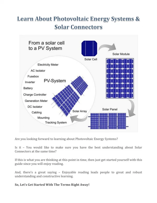
Photovoltaic Systems. Cells, Modules, and Arrays. Photovoltaic Cells • Current–Voltage (I–V) Curves • PV Device Response • Modules and Arrays Arizona Solar Power Society www.meetup.com/arizona-solar-power-society/. The basic building blocks for PV systems include cells, modules, and arrays.

Photovoltaic Systems
E N D
Presentation Transcript
Photovoltaic Systems Cells, Modules, and Arrays Photovoltaic Cells • Current–Voltage (I–V) Curves • PV Device Response • Modules and Arrays Arizona Solar Power Society www.meetup.com/arizona-solar-power-society/
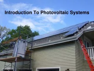
The basic building blocks for PV systems include cells, modules, and arrays.
Semiconductor materials with special electrical properties can be made by adding small amounts of other elements to silicon crystals.
The photovoltaic effect produces free electrons that must travel through conductors in order to recombine with electron voids, or “holes.”
Various PV materials and technologies produce different efficiencies.
Monocrystalline silicon wafers are sawn from grown cylindrical ingots.
Polycrystalline silicon wafers are sawn from cast rectangular ingots.
Several steps are involved in turning silicon wafers into PV cells.
Diffusion of phosphorous gas creates a thin n-type semiconductor layer over the entire surface of a p-type wafer.
The different materials, processes, and manufacturing steps produce a range of PV cell types.
An I-V curve illustrates the electrical output profile of a PV cell, module, or array at a specific operating condition.
Open-circuit voltage is easily measured with test instruments.
Using in-line and clamp-on ammeters are two methods of measuring short-circuit current.
A power versus voltage curve clearly shows the maximum power point.
Efficiency is a measure of how effectively a PV device converts solar power to electrical power.
A PV device can be modeled by a current source in parallel with a diode, with resistance in series and parallel.
Increasing series resistance in a PV system flattens the knee in the I-V curve, reducing maximum power, fill factor, and efficiency.
Decreasing shunt resistance reduces fill factor and efficiency and lowers maximum voltage, current, and power, but it does not affect short-circuit current.
Voltage increases rapidly up to about 200 W/m2, and then is almost constant. Current and maximum power increase proportionally with irradiance.
Increasing cell temperature decreases voltage, slightly increases current, and results in a net decrease in power.
Modules are constructed from PV cells that are encapsulated by several layers of protective materials.
An array is a group of PV modules integrated as a single power-generating unit.
Several modules may be connected together to form a panel, which is installed as a preassembled unit.
A junction box on the back of a module provides a protected location for electrical connections and bypass diodes.
PV cells or modules are connected in series strings to build voltage.
The overall I-V characteristics of a series string are dependent on the similarity of the current outputs of the individual PV devices.
Strings of PV cells or modules are connected in parallel to build current.
The overall I-V curve of PV devices in parallel depends on the similarity of the current outputs of the individual devices.
Modules are available in several sizes and shapes, including squares, rectangles, triangles, flexible units, and shingles.
Bypass diodes allow current to flow around devices that develop an open-circuit or high-resistance condition.
A bypass diode limits reverse current through PV devices, preventing excessive power loss and overheating.
Module labels must include performance ratings for the module and may include other information used to design a PV system.
Various test conditions can be used to evaluate module performance and may produce different results.
Modules are added in series to form strings or panels, which are then combined in parallel to form arrays.