Download
1 / 19
190 likes | 331 Views
The MEMSWAVE project focused on the design, modeling, and manufacturing of advanced microwave and millimeter-wave circuits on thin dielectric membranes supported by high-resistivity silicon substrates. Conducted during the second meeting in Uppsala on May 7-8, 1999, the project explored the creation of lumped elements, filters, and inductors. Key tasks included the characterization of structures up to 40 GHz and the validation of experimental results against simulations, thereby enhancing the performance of integrated microwave components.

E N D
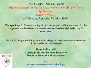
INCO-COPERNICUS ProjectMicromachined Circuits for Microwave and Millimeter Wave Applications(MEMSWAVE)2nd Meeting, Uppsala, 7-8 May 1999. Workpackage A: Manufacturing of microwave and millimeter wave circuits supported on thin dielectric membranes realized on high resistivity Si substrates.Task A.2: Design, modeling, manufacturing and microwave measurements of the passive circuit elementsRomolo MarcelliConsiglio Nazionale delle RicercheProgetto Sensori e MicrosistemiM2TMicrowave Microsystem Technology
WP A: Objective, Tasks and Deadlines • Design, realization and test of microwave and millimeter wave micromachined circuits on Si substrates 1st -21st month Tasks: • A.1: Dielectric membranes on high resistivity Si 1st - 9th month • A.2: Design, modeling and manufacturing of lumped elements 4th - 18th month • A.3: Millimeter wave filter demonstrator 7th - 21st month Microwave Microsystem Technology
General Description • Release of the feasibility on lumped elements and filters for microwave and millimeter wave frequencies on micromachined high resistivity Si wafers. • Design, realization and modeling of microstrip and coplanar circuits. The results obtained by characterization up to 40 GHz of lumped and filter structures will be used to design and realize 77 GHz demonstrators. • S-inductors, meander inductors, interdigital capacitors, spiral inductors, 15% bandwidth filters have to be studied. Microwave Microsystem Technology
Task A.2 Results • S and Meander inductors, and Interdigital Capacitors with eight and sixteen fingers have been simulated by means of the commercial software package HP Microwave Design System (HP-MDS) to exploit the possibilities for the simulation of lumped components utilizing coupled line elements, right angle bends and tee-junctions. • the agreement between experimental results and simulations is improved up to a satisfactory level by increasing the number of coupling effects considered within the structures. This is particularly important when components on membrane are exploited, i.e. for planar components characterized by a very low dielectric constant Microwave Microsystem Technology
Design criteria • Microstrip elements for approximating the behaviour of coplanar waveguide (CPW) configurations have been used to simulate the experimental components. • This choice is due to the fact that the microstrips are better known than the CPWs, and for this reason a huge number of analytical and numerical results are available . • The treatment by means of coupled microstrips is particularly effective when lumped elements realized on membranes are considered, because the planar arrangement of lines placed on a medium with a very small effective dielectric constant and having a separation between them in the order of few tens of micron is more sensitive to the planar coupling. Microwave Microsystem Technology
S-Inductor Microwave Microsystem Technology
Scattering parameter S21 for bulk S-inductor S21 parameter measured on a S-inductor realized on bulk GaAs (Exp, continuous line)compared with the two simulations described in the text, by including coupling only between ground and external lines (Bulk, dashed) and up to five coupled lines (Bulk5, points). Microwave Microsystem Technology
Scattering parameter S21 for S-inductor on membrane S21 parameter measured (Exp, continouous line) and simulated (Theoretical, dashed line) for the S-inductor realized on membrane. Microwave Microsystem Technology
Meander Inductor Meander inductor configuration for bulk GaAs and silicon micromachined substrates. The ground planes configuration is the same used for the S-inductor. Microwave Microsystem Technology
Scattering parameter S21 for meander inductor on bulk GaAs S21 parameter for the bulk meander inductor. Microwave Microsystem Technology
Scattering parameter S21 for meander inductor on membrane S21 parameter for the meander inductor on membrane. Microwave Microsystem Technology
Small interdigital capacitor (8 fingers) The eight fingers interdigital capacitor. Microwave Microsystem Technology
Scattering parameter S21 for the small interdigital capacitor on bulk GaAs S21 parameter for the eight fingers interdigital capacitor on bulk GaAs. The experimental result (Exp, continuous curve) is compared to the theoretical one (Theo, dashed line) composed by small elements and to the library software component (Lib, line with points). Microwave Microsystem Technology
Scattering parameter S21 for the small interdigital capacitor on membrane S21 parameter for the small capacitor on membrane. The difference between experimental, theoretical and library curves is now less pronounced with respect to the bulk circuit. Microwave Microsystem Technology
Big interdigital capacitor (16 fingers) Sixteen Fingers interdigital capacitor Microwave Microsystem Technology
Scattering parameter S21 for the big interdigital capacitor on bulk GaAs S21 parameter for the bulk sixteen fingers interdigital capacitor Microwave Microsystem Technology
Scattering parameter S21 for the big interdigital capacitor on membrane S21 parameter for the sixteen fingers interdigital capacitor on membrane Microwave Microsystem Technology
Working groups and resources • List of available human and technical resources and necessary complements for WP A: Microwave Microsystem Technology
Conclusions • Lumped elements have been designed and realized on bulk GaAs and on micromachined Si. • The agreement between measurements and theoretical data simulated by means of a coupled microstrip approach is quite good for most of them in the microwave range, especially when circuits on membranes are considered. • For frequencies higher than 30 GHz, a more precise simulation by using EM software will be performed, to account for more complicated coupling effects. Microwave Microsystem Technology