SIMIREL: Relays for All Applications
570 likes | 780 Views
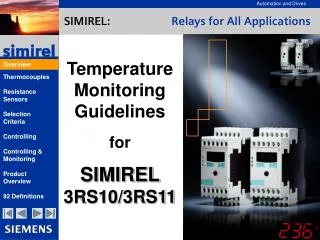
SIMIREL: Relays for All Applications. Temperature Monitoring Guidelines for SIMIREL 3RS10/3RS11. Overview. Overview: The Definition of Temperature. Temperature: One of the most important industrial measurements.

SIMIREL: Relays for All Applications
E N D
Presentation Transcript
SIMIREL: Relays for All Applications Temperature Monitoring Guidelines for SIMIREL 3RS10/3RS11 Overview
Overview: The Definition of Temperature Temperature: One of the most important industrial measurements. Physically speaking, heat is a means to measure the energy within a body. Such energy is stored in the disordered molecular and atomic movements of a body and increases with a simultaneous increase in temperature. The unit of measurement for temperature is Kelvin [K]. At 0°K (-273.5°C), all molecules within a body are at rest, i.e. its heat capacity is zero. The measurement of absolute temperature is generally stated in [°C] and temperature differences are stated in [K]. Thus, with many applications, temperature monitoring equals the (energy) monitoring of materials and system components. Overview
Overview: The Most Important Sensors • Sensors: • Thermocouples: Two interconnected metals which deliver a thermoelectric voltage independent of the ambient temperature. This voltage is a direct means of measurement for the difference between the measuring junction temperature T1 and the reference junction temperature T2. • Resistance sensors: These sensors change their resistance independent of the ambient temperature. They are generally made of platinum wire which is either fixed to a ceramic mould body (thin-film resistor) or is coiled onto a support within an oversheath. Resistance sensors are available as PTC resistors or as NTC resistors. Sensors for electrical temperature monitoring can be divided into: Overview
Thermocouples Mode of Operation Overview Reference Junction Compensation Application Areas Colour Codes Thermocouples
The Seebeck Effect: Thermoelectric Effect Regarding Thermoelectric Couples • A thermocouple generates a thermoelectric voltage independent of the used materials and the temperature difference between the measuring point and the reference junction. • No absolute temperatures can be measured with thermocouples. • The measuring point is the point at which the two metals are soldered, welded or twisted. • The reference junction is the point at which the two different conductors are connected to a further metal (e.g. copper). Thermocouples NiCr Reference junction Umeas T1 T2 Ni Measuring point Umeas = Uth T1 -Uth T2 The thermoelectric effect is the generation of an electromotive force (EMF) by ways of a temperature difference between the two connection junctions of two different metals which are part of a joint electric circuit.
Measuring Absolute Temperatures with the Help of “Reference Junction Compensation” • A “mere” temperature difference measurement between the measuring point and the reference junction can be carried out with the help of the thermoelectric effect. • To be able to evaluate the absolute temperature at the measuring junction, the ambient temperature of the reference junction must be established and added (e.g. with the help of a PT100). Thermocouples NiCr Internal reference junction T2 T1 Ni Measuring point PT100 Tabs= T1 (from Umeas = Uth T1 -Uth T2 ) + T2 (from RPT100 ) • All SIMIREL 3RS11 monitoring relays for thermocouples are already equipped with an internal reference junction compensation. • Thus, the ambient temperature of the evaluation device need not be taken into account. • A length extension of the thermoconductors is only permissible with the use of suitable conductors.
Long-term Short-term 100 500 1000 K 42 Nickel-Chrome / Nickel-Aluminium -180°C up to 1350 °C 0°C up to 1100 °C 43 39 -250°C up to 400°C -185°C up to 300°C Copper / Copper-Nickel - 46 - T 54 -180°C up to 750°C 59 56 J 20°C up to 700°C Iron / Copper-Nickel 39 0°C up to 1100 °C -270°C up to 1300 °C 30 Nickel-Chrome-Silicium / Nickel-Silicium N 38 -40°C up to 900°C E Nickel-Chrome / Copper-Nickel - 68 81 0°C up to 800°C Overview:Thermocouples DIN EN 60584-2 (1994), IEC 584-2 (1992) Element/ alloy Voltage changes per °C in µV at °C: Applicationtemperatures Properties / Notes Thermocouples • The most commonly used thermocouple • For oxidising atmospheres with a large application temperature range • Large hysteresis • Rarely used • For low application temperatures • Good properties concerning high humidity • Commonly used in the plastics industry • Also used with exposed measuring junctions in reduced atmospheres • Corrodes with low temperatures, • oxidises with high temperatures • (Still) rarely used • Extremely stable output signal • High resistance against temperature change strains • Largest thermoelectric voltage per °C • Also used with exposed measuring junctions within a vacuum or slightly oxidising atmospheres
Application Areas of Thermocouple and Extension- Wires DIN 43722 (1994), IEC 584-3 (1989) International identification letters Max. temperature of the conducting wires Temperature range of performance Properties / Notes K Thermo- conductor KX 900°C -25°C up to +200°C The extension wire is made of the same material as the thermoelectric couple, i.e. thermal faults are minimized. Thermocouples Extension conductor KCB 900°C 0°C up to +100°C Cost-favorable alternative for applications within these temperature limits (Copper - Copper/Nickel). T Thermo- conductor TX 300°C -25°C up to +200°C The extension wire is made of the same material as the Thermocouple. Extension wire is not accounted for (cost-favorable). J Thermo- conductor JX 500°C -25°C up to +200°C The extension wire is made of the same material as the Thermocouple. Extension conductors are not accounted for (cost-favorable). N Thermo- conductor NX 900°C -25°C up to +200°C The extension wire is made of the same material as the thermocouple. Extension conductor NC 900°C 0°C up to +150°C Extension wires are not normally used. The accuracy advantage of this thermocouples would be lost. E Thermo- conductor EX 500°C -25°C up to +200°C The extension wire is made of the same material as the thermocouple. Extension conductors are not accounted for.
Color Codes for Thermocouples and Extension Wires DIN 43722 (1994), IEC 584-3 (1989) ANSI MC96.1 International identification letters German and international color codes Intern. color codes for intrinsically safe electric circuits United States K Thermo- wire KX + - + - Thermocouples + - Green Green Yel Green Blue Brown Red Equalising- wire KCB + - + - Green Green Green Blue T Thermo- wire TX + - + - + - Brown Brown Blue Brown Blue Brown Red J Thermo- wire JX + - + - + - Black Black White Black Blue Brown Red N Thermo- wire NX + - + - Pink Pink Blue Pink Equalising- wire NC + - + - Pink Pink Blue Pink E Thermo- wire EX + - + - + - Purple Purple Purple Brown Blue Purple Red
Resistance Thermometers Color Codes Connection Methods 2-Conductor Method 3-Conductor Method Resistance Sensors
Red Red Red Blue Blue Red Red Red RT RT RT RT White White White White White Color Codes of Resistance Thermometers In general, four different connection methods for resistance thermometers are possible: 4-conductor circuit with blind loop 2-conductor circuit 3-conductor circuit 4-conductor circuit Resistance Sensors In accordance with DIN 60751 (1996) and IEC751 (1983)
Overview of the Connection Methods for Resistance Sensors 2-conductor measuring 3-conductor measuring 4-conductor measuring RL RL RL I I I RL RL Resistance Sensors PT 100 U PT 100 U PT 100 U RL I I I RL RL RL • Conductor resistance and sensor resistance are added together • Systematic fault (dependent of:conductor length, conductor cross section and conductive material) • State of the art solution • Conductor resistance is not included in the measurement • Precondition: All conductors have the same resistance • Decreasing use • Conductor resistance is not included in the measurement • Conductors may have a differing resistance
R1 R2 RL Uv UB IR IT RL RT I R3 Two-Conductor Method for Resistance Sensors Example: Classical Wheatstone-bridge with the two voltage dividers R1 and RT as well as R2 and R3 . Precondition: The conductor resistance values RL are negligible. Resistance Sensors For R1 / RT = R2 / R3 it is assumed that: UB = 0 The bridge is assumed to be balanced when : UB = 0.If the resistance RTchanges, the measuring voltage UBchanges proportionally. Advantage of the Wheatstone-bridge: The value of the supply voltage is not included in the measurement.
R1 R2 IT Uv RL UB RT IR RL R3 I RL Three-Conductor Method for Resistance Sensors Example: Classical Wheatstone-bridge with three-conductor circuit and the two voltage dividers R1 and RT as well as R2 and R3, each of which also comprises the conductor resistance RL. Precondition: All conductor resistance RL values are equally high. Resistance Sensors For R1= R2and the balanced bridge it is assumed that: UB= 0 andIT= IR • Advantages: • The value of the supply voltage is not included in the measurement. • The conductor resistance has no influence on UB as each of the two voltage dividers comprise a conductor resistance RL.
Selection Criteria for Thermocouples and Resistance Thermometers Properties in Comparison Types of Construction Application Areas Characteristic Curves Selection Criteria
Properties of Thermoelectric Cells and Resistance Thermometers Thermocouples Resistance Sensors Accuracy Good Very good Application Areas Large temperature range Small temperature range Price Cost-favorable More expensive Measuring Point Small, point-shaped Covering the length of the measuring resistance Selection Criteria Response Times Very short Relatively long Reference Junction Required Not required Surface Measurement Very good suitability Limited suitability Vibration Resistance Very robust Limited suitability Supply of Measuring Current Not required Required Spontaneous Heating Does not occur Insignificant fault occurrence Long-Term Stability Satisfactory Excellent Robustness Very good Good Connection Lines Special materials Standard cables
Selection of Some Types of Construction of Temperature Sensors Resistance thermometer Thermocouples Angular thermocouples Selection Criteria Sheathed thermocouples (bendable) Sheathed resistance thermometer Wire-coiled PT100 Foil thermocouples Embedded resistance thermometer
Metal welding, salt baths Cooling and ventilation technology Enamel and ceramic tempering furnaces Exhaust temperatures Ambient temperatures Boiler plants Solid bodies (e.g. film sealing jaws) Combustion chamber monitoring Application Areas of Thermocouples and Resistance Thermometers Resistance thermometers X X X X X Selection Criteria Sheathed resistance thermometers (bendable) X X X X Thermo- couples X X X X Sheathed thermo-couples(bendable) X X X X X Angular thermo-couples X Temperature
U [mV] R [] NTC 80 4000 Type E 60 3000 PT1000 Type J 40 2000 Type K 20 1000 PT100 0 250 500 750 T [°C] Characteristic Curves of Some Thermocouples and Resistance Thermometers Conversion of °C to °F: °C = (°F-32)/1.8 °F = 1.8°C+32 Selection Criteria
Controlling The Control Circuit 2-Position Controllers 3-Position Controllers PID Controllers with Clocking Output PID Controllers with Analogue Output Controllers with Integrated Automatic Adjustment Controlling
Disturbance variables Z Control point Final controlling element (heating) Control path (system) Measuring junction Measuring device (sensor) Control Circuit Setpoint value adjuster reference input element (SPC) Intensifier (SC-contactor) Referencejunction Setpoint value The Control Circuit The control circuit serves the adjustment of a pre-specified measurement to the desired value and the limitation of such realised value within a reasonable tolerance range. Controlling Controlling means: A constant comparison between the measured and required value and, in cases of deviations, the necessary correction of such deviation with the help of the final controlling element.
TMax TSetpoint e.g. 80°C Hysteresis range Hysteresis value TMax = Maximum attainable temperature; limited by the heating power TSetpoint = Switch-off temperature t Start = Preheating time t 0= Controlling clocking time t t Start t 0 Two-Position Controller with Hysteresis, Shown in a “Heating” Application When the TSetpoint temperature is attained, the two-position controller switches off the heating. As soon as the temperature has attained the hysteresis value, the heating is switched back on again. Controlling • Examples: • Heating chambers for stress tests of electronic modules • Water heating within instantaneous water heaters, pipe heat tracings for frost protection, ... • Can analogously also be used for cooling applications, e.g. with cooling and air-conditioning systems, switchgear cabinets, water-cooled operating mechanisms and lasers, ...
L1 S1 11 12 A1 A3 11 13 K1 K1 T1 J H1 L2 T2 14 12 T3 A2 NSB01333b Example of a 2-Position Controller with Hysteresis: Frost Protection with Pipe Heat Tracings The two-position controller switches on the pipe heat tracing at 5°C. As soon as the temperature has reached the hysteresis value of 7°C, the pipe heat tracing is switched back off again. Switch-on value Controlling Hysteresis value (Illustration with appliedsupply voltage, temperature lies above the threshold value) • Advantages of Simirel 3RS1010-1CD00: • Cost-favorable solution • Simple construction, easy setting • Can also be used for cooling applications, e.g. with cooling and air-conditioning systems, switchgear cabinets, water-cooled operating mechanisms and lasers, ...
Advantage: • Short preheating time and long clocking time with few switching cycles and little current variations Example: • Heat treatment ovens for metal processing • Decompression furnaces 3-Position Controller with Two Filament Windings and Hysteresis, Shown in a “Heating” Application The three-position controller switches the first heating off when the temperature T1 is attained and the second heating when the temperature TSetpoint is attained. (TSetpoint approx. 50 % of TMax (two heatings) and approx. 90 % of TMax (one heating).) TMax = Maximum attainable temperature; limited by the heating power TSetpoint = Switch-off temperature of the second heating T1 = Switch-off temperature of the first heating t Start= Preheating time t 0= Controlling clocking time TMax TSetpoint e.g. 130°C Controlling Hysteresis range Hysteresis range T1 e.g. 110°C t t Start t 0
L1 S1 15 25 33 18 34 26 28 16 H11 K15 K25 H15 H25 H33 L2 Example of a 3-Position Controller with Hysteresis:Temperature Controlling in Heat Treatment Ovens • Mode of Operation: • Required task: Temperature control of two filament windings within a heat treatment oven with the help of a three-position controller. • Wiring diagram of 3RS1040: • Solution with SIMIREL 3RS1040/3RS1140 : • In contrast to the classical two-position controller with only one filament winding, this principle both works with a heating power whose power only generates slow temperature changes in a stationary process state as well as with a second, stronger filament winding which is able to generate fast heating processes. After the preheating phase, i.e. after the process temperature has been attained, the second filament winding may be switched off. • The controller will only switch the second heating back on again if the first off-switching temperature is undershot, e.g. when opening the oven door. During normal operation, merely the poorer performing heating is switched on in accordance with the heating requirements. Controlling • Advantages and special characteristics: • - The preheating phase is significantly shortened. • - Current and temperature fluctuations are kept insignificant during the entire course of operation. • - The switching frequency is reduced as the heating power can be adjusted to the process requirements relatively accurately.
T T Setpoint T Actual t Relay “On” Relay “Off” PID Controller with On-Off Control The PID controller with On-Off Control changes its On-Off ratio depending on the difference between the setpoint value and the actual value. Controlling Intervals are thus continuously becoming longer while heating times become shorter.
PID Controller with Analog Output The PID controller with analog output changes its correcting variable depending of the difference between the setpoint value and the actual value. T Setpoint T T Actual Controlling t Umax Correcting variable Umin t Correcting values are thus continuously becoming smaller. Umin keeps the temperature at TSetpoint .
Manual setting Automatic adjustment ON/OFF The PID constantsare determined Controller reaction after calculation of PID constants Manual setting Temperature Controllers with Auto Tuning • Many controllers are equipped with a system with which they can determine the required PID parameters independently. To do this, they switch the heating completely on and measure the proportional factor, dwell time and lead time (self-learning). Setpoint value Alarm setpoint value Proportional band Dwell time Controlling Lead time Compensation variable • In addition, there are controller types which also continuously optimise these parameters (self-optimising). Input value deferral
Controlling & Monitoring Why is Control Monitoring Necessary? Monitoring with 3RS17 Monitoring with 3RS10/3RS11 Controlling & Monitoring
Why is Temperature Monitoring Necessary Despite Controller Devices? The control circuit is made up of a chain of various hardware and software components. Disturbance variables Z Control point Final controlling element (heating) Control path (system) Measuring junction Measuring device (sensor) Control Circuit Setpoint value adjuster reference input element (SPC) Controlling & Monitoring Interruption, e.g. breakage Intensifier (SC-contactor) Reference junction Setpoint value In cases of component or connection line failures, in cases of software faults as well as in cases of too large disturbance variables, the controller can no longer guarantee a compliance with the temperature limits.
Controller Devices with Additional Temperature Monitoring and Second Sensor Disturbance variables Z Control point Final controlling element (heating) Control path (system) Measuring junction Measuring devices (2 sensors) Control Circuit Setpoint value adjuster reference input element (SPC) Intensifier (SC-contactor) Reference junction Controlling & Monitoring Temperature monitoring relay (3RS10/3RS11) Warning light • Advantages: • The second sensor offers additional protection. • The monitoring of second sensor operates in parallel with the control circuit. Thus, the existing control system need not be altered.
Controller Devices with 3RS17 Temperature Converter and One Sensor (Planned) Disturbance variables Z Control point Final controlling element (heating) Control path (system) Measuring junction Measuring device (1 sensor) Control Circuit Setpoint value adjuster reference input element (SPC) Intesifier (SC-contactor) Referencejunction Controlling & Monitoring 0/4-20mA, 0-10V Temperature monitoring relay (3RS17) Warning light • Advantages: • SPC connection and temperature limiter within one device • Warning signal when the first temperature limit is reached • Disruption of the control system‘s energy supply when theset maximum temperature is exceeded
3RS10/3RS11 Device Overview Overview Split by Sensors Overview Split by Scopes of Functionality Product Details Analog devices with 1 threshold value Analog devices with 2 threshold values Digital devices with 2 threshold values Setting Parameters Function Diagrams Establishment of an Average Temperature Product Overview
Product Overview Split by Sensors • For Thermocouples • Voltage potential • proportional to the temperature - Type J -99°C up to + 999°C - Type K -99°C up to +999°C - Type N -99°C up to + 999°C - Type T -99°C up to + 400°C - Type E -99°C up to + 999°C • For Resistance Sensors • Resistance value • proportional to the temperature Product Overview - PT100 -50°C up to + 500°C - PT1000 -50°C up to + 500°C - KTY 83 -50°C up to + 175°C - KTY 84 -40°C up to + 300°C - NTC +80°C up to + 160°C
Product Overview Split by Functionality Analog Devices with One Setpoint Value Analog Devices with Two Setpoint Values Digital Devices Closed current principle Working/closed current principle 2- or 3-position controller Product Overview Setting of limit values and hysteresis via a rotary potentiometer Very easy parameterisation with rotary switch and two pushbuttons
L1 A1 11 13 3RS1000/1010 1100/1101 1110/1111 T1/+ A2 12 14 T2/- Trip Signal -K1 -H2 TC / RS Product Details: Analog Devices with One Threshold Value Product Overview One threshold value with adjustable hysteresis • The top-seller • PT100, Type J, Type K • Closed current principle • Overflow or underflow • Different temperature ranges
L1 11 A1 23 3RS1020/1030 1120/1121 1130/1131 T1/+ A2 24 12 14 T2/- Signal -H2 Alarm Trip -H3 -K1 TC / RS Product Details: Analog Devices with Two Setpoint Values Product Overview Two threshold values and adjustable hysteresis • Warning and off-switching • PT100, Type J, Type K • Working or closed current principle • Overflow or underflow • Different temperature ranges
L1 A1 15 25 33 3RS1040/1041 1140 34 16 18 26 28 T1/+ A2 T2/- Trip -K1 -K2 Display -H1 TC / RS -H3 -H2 Wire breakage/Short circuit Product Details: Digital Devices with Two Setpoint Values Product Overview Two threshold values and ajdustable hysteresis • The expert • For all common sensors • LED display • Overflow, underflow, window monitoring • Adjustable hysteresis and delay time • 1CO + 1CO + 1NO
Down Up Parameter selection Digital Devices:Parameterisation Example: 3RS1040 Rotary selector switch for parameter selection Pushbutton for “Up” or “Down” 1. Threshold value J1 2. Threshold value J2 3. Hysteresis 4. Delay time 5. Working principle WORKING CLOSED Product Overview 6. Mode of operation UNDERFLOW OVERFLOW WINDOW 7. Sensor type PT1000 PT100 KTY83 KTY84 NTC 8. Operation (RUN) ACTUAL TEMPERATURE
Function Diagram:Temperature Overshoot Mode of operation: working current principle Mode of operation: closed current principle J1 < J2 J1 < J2 J2 J2 J1 J1 Us Us Product Overview K1 K1 Delay Delay K2 K2 Delay Delay
Function Diagram: Temperature Undershoot Mode of operation: working current principle Mode of operation: closed current principle J1 > J2 J1 > J2 J1 J1 J2 J2 Us Us Product Overview K1 K1 Delay Delay K2 K2 Delay Delay
Delay Delay Function Diagram:Window Monitoring Mode of operation: working current principle Mode of operation: closed current principle J1 < J2 J1 < J2 J2 J2 J1 > J2 J1 J1 Us Us Product Overview K1 K1 Delay K2 K2 Delay
Establishing the Average Temperature Within a Medium with the Help of Several Sensors In many cases, the average temperature within a medium or that on a specific surface is of special interest. Such measurement can easily be realised with the use of the wiring diagram illustrated below as well as a 3RS11 temperature monitoring relay. T1 Measuring point 1 T2 Measuring point 2 T3 Measuring point 3 • Mode of operation: • As soon as different temperatures are detected between the thermoelectric cells, equalising currents will flow within the conductors. They serve to ensure that the average value of the single voltages is realised at the connection junction, given that all conductors have the same conductive resistance. Tips & Tricks
92 Definitions: Would You Have Known Them? Almost everything you needto know about temperaturemonitoring relevant definitions From A - Z 92 Definitions
Alumel Trading name of the high-temperature resistant nickel alloy NiAl which, together with chromel, forms the Type K thermocouple. Adjustment time Compensation device Ceramic insulation Black body Calorie [cal] Blind loop Absolute zero Chromel Ensures that the measured value is largely independent of influential variables (disturbance variables). Quantity of energy required to heat 1 gram of water from 14°C to 15°C. A body which absorbs all occurring radiation and emits the maximum thermal radiation. Trading name of the high-temperature resistant nickel alloy NiAl which, together with alumel, forms the Type K thermoelectric couple. Additional conductor loop from the measuring device to the sensor used to compensate conductor resistance and parasitic voltages. The lowest temperature a substance can have. It is also the starting point of the Kelvin scale (-273.15°C). Time period between a sudden change of the input size and the adjustment of the output size to its balancing setpoint value. High-temperature resistant ceramics (sintered aluminium oxide, corundum, silmanite or magnesium oxide). It is used as a material for protective pipes or for small insulating rods of thermometers. Definition of Terms Abs - Com 92 Definitions
Depth of immersion EMF Equalising conductors Emissivity coefficient External reference junction temperature Drift Earthedmeasuring junction Exposed measuring junction Constantan The length of the thermometer component which is exposed to the measuring value. Electromotive Force which, e.g., effects a voltage difference by ways of thermoelectric energy within a conductor. Ratio of the optical radiated power of a substance compared with a black body of the same temperature. Reference junction temperature which is used for the determination or establishment of the signal voltage when thermocouples are applied. Conductors for a cost-favourable length expansion of measuring conductors for thermocouples (limited measuring ranges). Copper-Nickel alloy which was developed as a material for electric resistance. Yet, it is also used as a negative arm for the Type K and Type T thermoelectric couples. Shift of a measuring signal over a long period of time. Thermocouples whose measuring junction is welded with the protective cover (same potential as the system). The measuring junction of a thermocouples is in direct contact with the medium to be measured without any mechanical protection (to facilitate a fast response behaviour). Connecting head Cover or casing for sealing protective pipes used with thermocouples or resistance thermometers. Definition of Terms Con - Ext 92 Definitions
Hot junction Internal conductors Intrinsically safe electric circuits Insulated measuring junction Isothermal Indicial response IST- 90 Kelvin scale Joule Fahrenheit Designation for the measuring junction of a thermocouple. Electrical connection between the actual measuring resistance and the external connections of the sensor element. The hot junction of thermocouples which is electrically insulated against the protective cover or the tubular jacket. State of a homogeneous and constant temperature. Unit of measurement for energy. International temperature scale of 1990. Anglo-Saxon temperature scale (32°F = 0°C / 212°F = 100°C). Representation of the temporal course of a measured value or the output signal after a sudden change of the measured variable. The switching circuit is arranged in such a way that sufficient electric energy for the igniting of flammable substances can under no circumstances whatsoever be transferred or saved. Temperature scale for the measured variable of the thermodynamic temperature. The scale definition starts with absolute zero (-273.15°C). Definition of Terms Fah - Kel 92 Definitions
Measured value Life zero Linearity Measuring junction Limit conditions Measuring fault Loop resistance Measuring point Measured variable Measured value hysteresis value Hysteresis: Differential sum of the measured values for the same value of the measured variable when this value is reached in increasing or decreasing direction. This minimum current of 4mA is normally used for power supply and conductor monitoring; values of under 4mA are a proof for occurred faults. Directly proportional ratio of an instrument‘s display value and the measured value. Maximum ambient conditions a thermometer can be exposed to without consequential damage or deterioration. Total resistance of the measuring loop, including the measuring element, contact resistance and conductor resistance. Connection points of the welded, soldered or twisted thermoelectric arms of a thermocouple. Point within a medium or a substance at which the measurement is carried out. A feature whose value is to be determined with the help of a measurement (e.g. temperature). Undesired deviation between the actual value of a measuring device and its setpoint value. Value of a measuring unit determined by way of a measurement. It is made up of the product of numeric value and unit. Definition of Terms Lif - Mea 92 Definitions
Negative temperature coefficient (NTC) Measuring range Measuring resistor NTC resistors Medium temperature coefficient a Müller bridge Nominal resistance Overtravel deviation Noise Nicrosil-Nisil Type N thermoelectric couple which is made of a Nickel-Chrome alloy and a Nickel-Silicium alloy. Maximum value range of a measuring device. Sensor element of a resistance thermometer whose electric resistance depends on the temperature. Medium relative resistance change per Kelvin within the range of 0°C and 100°C. Highly precise measuring bridge configuration for resistance thermometers with 3-conductor circuits. Sensors with a negative temperature coefficient. With an increase in temperature, the electric resistance decreases (NTC). Measuring deviation due to a temporal overtravel of the measured value or the output signal compared with a sudden change of the measured variable. Undesired effect caused by electromagnetic radiation of the signal conductors. Setpoint value of the temperature-dependent resistance at 0°C. Ratio of the temperature difference and the resistance difference of NTC resistors. With an increase in temperature, the resistance decreases. Definition of Terms Mea - Ove 92 Definitions
Peltier effect Polarity Reference junction Positive temperature coefficient (PTC) Pyrometry PT100 Reference junction thermostat PTC resistor Sensors with a positive temperature coefficient. With an increase in temperature, the electric resistance also increases (PTC). Reversion of the Seebeck effect. With a current-imposed conductor consisting of two metals, one connection junction is supplied with heat while the other one is subjected to heat dissipation. Designation of the plus and minus arms of thermocouples. Ratio of the temperature difference and the resistance difference of PTC resistors. With an increase in temperature, the resistance increases. Connection junction of the thermocouples lying on the reference temperature. Temperature measurement with the help of radiation pyrometers. The thermal radiation of a body is used for temperature measurement. Platinum resistor element with a nominal resistance of 100 Ohm at 0°C. Externally tempered measuring circuit with a constant and known temperature which is taken as a reference for reference junction compensation. Reference junction compensation Adjustment of the output signal of a thermocouple if the reference junction is not specified at 0°C. Definition of Terms Pel - Ref 92 Definitions