Download
1 / 54
1.01k likes | 3.26k Views
Overview of Digital Relays. ISO Training John S. Levine, P.E. Levine Lectronics & Lectric John@L-3.com www.L-3.com. ISO Training July 22, 2008 Outline. Introduction Overview of Digital Relays Tools Enervista Launchpad PowerPoint presentations at GE Digital Relays Protection Basics

E N D
Overview of Digital Relays ISO Training John S. Levine, P.E. Levine Lectronics & Lectric John@L-3.com www.L-3.com
ISO Training July 22, 2008Outline • Introduction • Overview of Digital Relays • Tools • Enervista Launchpad • PowerPoint presentations at • GE Digital Relays • Protection Basics • SR489 • GE Multilin G30 Training • Post Glover NGR Training • ANSI Symbols handout • Conversion of Electro-Mechanical to Electronic sheet • GE Multilin Training CD’s
Trends • 75% of Installed Base of Relays are Electromechanical • 90% of New Relays Purchased are Digital/Electronic • Lingering Issue of “Putting All Eggs In One Basket” • “No Backup” • “Like to See Disk Move” • Solve with Backup (such as DIAC as backup to SR760 or F60) • Gain Excellent Accuracy and No Setting Drift • Manufacturers have Created Relay Families, thus reducing maintenance, O&M costs and training.
Microprocessor-Relay Benefits • Multi-Function Protection Cost Effectiveness • Configurable/Programmable Logic • User Configurable Time Current Curves • Self-Testing of Relay’s Algorithms with Alarm Contact • Reduce Periodic Testing • Every 1-2 years for Electromechanical • Every 5-10 years for Digital (or More!) • Improved System Data • Fault Location & Reporting - Waveform Capturing • Internal Operation Data - Metering • Breaker Health Monitoring - Demand Interval Records • Sequence of Event Reporting
Microprocessor-Relay Benefits • Flexible Settings • Multiple Setting Levels • Communication Capabilities • Local via Keypad • Remote via Computer and Modem • Networks can be created • Reduced Panel Space & Wiring • Compact Packaging • Tested at Factory • Eliminate Component Panel Metering
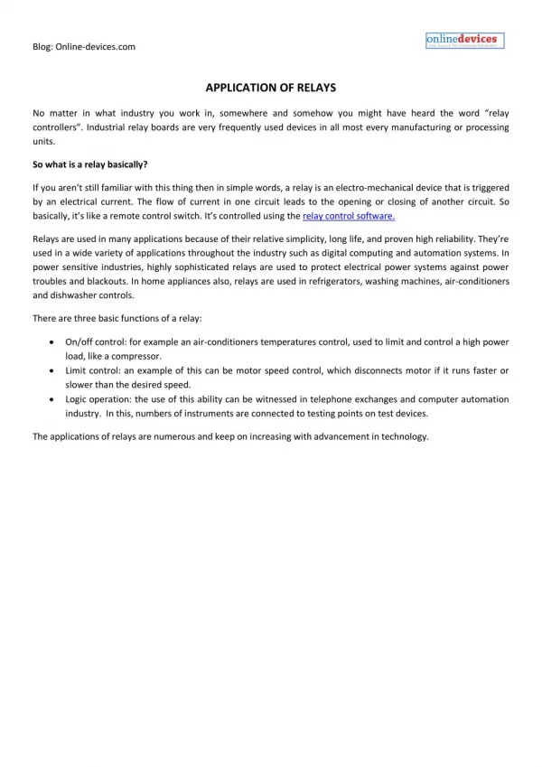
Digital Relays - Areas Of Use • Distribution Feeder Protection • Reclosing • Down Conductor Detection • Breaker Failure Protection • Generator Protection • Transmission Line Protection • Transformer Protection • Bus Protection • Motor Protection
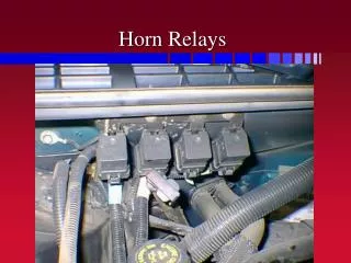
NEW OLD
Programmability • Digital Relays Have: • Programmable Inputs • Programmable Outputs (ALARM & TRIP) • Programmable Logic • Boolean Logic - AND, OR, NOT Logic • Programmable Time Current Curves
Metering • 0.25 - 5% Accuracy on I & V • Typical Values • Can Be Accessed Locally or Remotely • Some Relays Have Analog Outputs Proportional to Metering Values (i.e. 0-1mA) • Min & Max Values with Date & Time Stamp • Harmonic Values of I • Symmetrical Components • Operation Counters • Breaker Position • Current • Voltage • Watts, Vars, PF • Frequency • kWh, kVarh • Phase Angles
Other Monitoring • Breaker Health Monitoring • Cumulative I2T or IT • Activate Alarm At Set Level • Demand Interval Reporting • 15, 30, 60 Minute Intervals over Several Days • I, Watts, Vars, VA, PF • Peak Values Recorded • Date & Time Stamped • Trip & Close Coil Monitor • Fault Location & Fault Reporting
Sequence Of Events Recording • Events Stored with Date & Time: • Alarms • Contact Operations • Logins & Logouts • Waveform Captures • Remote Operations • Resets • Setting Changes • Last 100-1000 Events Stored
Settings • Easier Than Electromechanical/Static • Flexible settings • Relays Have Multiple Setting Groups • Can be Switched with Input Contacts or Remotely • Settings Are Stored in Files and Down Loaded to Relay with PC • Easy to Copy Existing Setting Files and Modify • Accurate Implementation of Settings • No Overtravel • No Large Drifts in Set Points • Selection of Reset Times • Fast (Digital) or Slow (Electromechanical)
Phase A Phase B Phase C Alarm 87 Local Communications • Thru Keypad, Up, Down Arrows, Enter/Select Keys or RS232 Port on Relay • Local LED Display • Reset Key/Button • LED Targets • Password Protection Phase TOC1 OP DN UP ENTER
DSL or Telephone Modem RELAY Modem Remote Communications • Thru Rear RS232 or RS485 Port Using Standard Modem Software or Relay Manufacturer’s Communication Software • Password Protection • 10Mbps Ethernet Connections - Wire or Fiber • Multiple Protocol Support (DNP3.0, Modbus RTU, Devicenet, Profibus, and IEC 61850)
Memory Map Example Group Address Description Current 0300 Phase A Current 0301 Phase B Current 0302 Phase C Current 030D Phase A Differential 030E Phase B Differential 030F Phase C Differential
Reset Data Min/Max, Demand, etc. Reset Targets Operate Output Contacts Trip & Close Trigger Waveform Capture Set Date & Time Force Input Contact Operation Block Relay Functions Perform Setting Changes Available Control by Digital Relaysvia Communications & Protocols
Maintenance Benefits • Self-Test Capabilities • Remote Communications • Easy Setting Changes • One Model Could Be Used for Several Applications • No Setting Drift of Digital Relay • Reduced Wiring • Flash Memory • Upgradeable Firmware
DIAC,DIFC,DSFC Single Phase Overcurrent Protection • Digital Overcurrent Relay Platform w/ True RMS Overcurrent Measurement (50/51) • Replace IAC, IFC and SFC relays. . . • Self Powered (no DC Battery Required) • Same case size, no metal modifications • Simply add surge ground lead • User Selection of 16 curve characteristics • Exact Duplication of IAC51, IAC53 & IAC77 Characteristics • Instantaneous Overcurrent Delay Setting • Reset Characteristic Selection (Fast or E/M) • Draw-out Case with Test Facilities • Retrofit existing IAC, IFC and SFC Cases • Very Low Burden (1.8VA) • No Communications
SR760 - Feeder Protection • 16 Samples/Cycle • 3 Phase & Ground Overcurrent Protection • Programmable Time Current Curves • Over/Under Voltage • Over/Under Frequency • Synch Check • 4 Shot Reclosing • Fault Location • 4 Setting Groups • Analog Outputs/Input (8/1) • Metering I, V, W, Var, VA, PF, Hz, Wh, Varh • Waveform Capturing • RS485 Communications • DNP3.0 and Modbus RTU Protocols • Flash Memory for Upgrades • Drawout Construction • Programmable Display • Simulation Test Mode • IRIG-B Time Sync
SR489 Generator Management Relay Product Overview • Ideal Protection for Induction and Synchronous Generators at 25, 50 and 60Hz • Complete Generator Protection including: • Generator Stator Differential • 2 Zone Distance Backup • 100% Stator Ground • High speed sampling, 12 samples per cycle • Drawout Case Installation • Powerful Fault Recording: Waveform, Sequence of Events • Ethernet and Serial Communications • EnerVista Suite of Software supported • Metering of all important parameters
SR489 Protection Functions • Protection Functions Include: • Generator Stator Differential • Backup Distance Protection • 100% Stator Ground • Generator Unbalance • Loss of Excitation • Accidental Energization • Breaker Fail • Phase Overcurrent – Voltage Restraint • Neutral Inst. / Timed Overcurrent • Neg. Sequence Overcurrent • Under / Over Voltage • Under / Over Frequency • Generator Thermal Model • RTD Temperature • Overexcitation – Volts/Hertz
SR745 - Transformer Protection • 64 Samples/Cycle • 3 Phase Differential Protection • 3 Phase & Ground Overcurrent per Winding • Adaptive Time Overcurrent • Programmable Time Current Curves • Loss of Life Monitoring (Opt.) • 4 Setting Groups • Harmonic Analysis (up to 25st) • Angle & Zero Sequence Compensation • Analog Outputs/Input (Opt.) • 2 & 3 Winding Models • Configurable Logic • Waveform Capturing & Playback • Simulation Test Mode • Flash Memory for Upgrades • RS485 Communications • Modbus RTU and DNP3.0 Protocols • Programmable Display • Dynamic CT Ratio Correction • IRIG-B Time Sync SR745 Transformer Management Relay
The UR Family - One Common Architecture TRANSMISSION DISTRIBUTION • L60 (Transmission Line: Phase Comparison) • L90 (Transmission Line: Current Differential) • D30, D60, abd D90 (Transmission Line: Distance) • B30 and B90 (Busbar: 6 to 24 Feeder) • F35 (Feeder: Multiple Feeders - Basic Protection) • F60 (Feeder: Comprehensive w Hi-Z) • T60 (Transformer: Comprehensive) • C30 (Control IED) • C60 (Breaker Management IED) GENERATION / MOTOR • G30 and G60 (Generator: Comprehensive) • T60 and T35 (Transformer: Basic up to 6 Windings) • B30 and B90 (Busbar: Comprehensive up to 24 Feeders) • M60 (Motor) “The Engine for Substation / Plant Automation”
Physical Realization 19’’ Chassis (4RU high) or Vertical Unit Modules Power Supply COMMUNICATIONS DSP & Magnetics DSP processor + CT/VTs DIGITAL I/O Status Inputs / Control Outputs ANALOG I/O Analog Transducer I/O CPU Main Processor Modular HMI (Hinged & Removeable) High-Speed Data Bus
‘Upgradeability’/Serviceability ‘Plug n Play’ Easy Module Draw-out Module Keying Field Wiring Undisturbed CT Shorting ‘Clips’ CPU Automatically Recognizes New Hardware upon Initialization
Example: Busbar with 5 Feeders 79 79 79 79 79
Example: Inputs in to UR Relay CT2 CT1 CT4 CT5 CT3 VT1
Example: UR Relay using Sources 79 79 79 79 79 Universal Relay 50-Inst, 51-Time, 81-Freq, 79- Reclose
F60 Feeder Protection • Single Feeder Protection with Bus Voltage • Phase, Neutral & Ground Time Overcurrent (51P, 51N, 51G) • Phase, Neutral & Ground Inst.Overcurrent (50P, 50N, 50G) • Negative Sequence Time Overcurrent (51_2) • Negative Sequence Inst.Overcurrent (50_2) • Fast or EM Reset Characteristic for TOC Elements • Phase, Neutral and Negative Sequence Directional Control • Phase Undervoltage & Overvoltage • Negative Sequence Overvoltage • Underfrequency (6 elements) • Overfrequency • 4 Shot Autoreclosing with Sequence Coordination • VT Fuse Failure • Programmable Fast & Slow Operations • Breaker Failure (50BF) • Synchrocheck (25) • Cold Load Pickup • Breaker Arcing Current (I2t) • Data Logger & Fault Location • Transducer I/O • FlexLogic with gates and timers • Programmable LED Panels • Metering • Harmonic Metering (up to 25th) • Oscillography • Event Recorder & Fault Records • Demand Recording • DNP, Modbus RTU & UCA Protocols • 8 Setting Groups • Down Conductor Detection (Optional)
F35 Multiple Feeder Protection • 5 Feeder Protection with Bus Voltage • 6 Feeder Protection w/o Bus Voltage • Programmable LED Panels • (6) Phase TOC elements • (12) Phase IOC elements • (6) Neutral TOC elements • (12) Neutral IOC elements • (6) Ground TOC elements • (12) Ground IOC elements • (1) Phase Undervoltage element • (6) Underfrequency elements • (6) Autoreclosing elements • FlexLogic with gates and timers • Transducer I/O • Data Logger • Metering • Oscillography • Event Recorder • Demand Recording • DNP, Modbus RTU & UCA Protocols • 8 Setting Groups
LED Programmability
T60 Transformer Protection • Up to 4 Restraint Inputs • 2 & 3 Restraint with Three Phase Voltage Inputs • 4 Restraint without Voltage Inputs • Dual Slope Percent Differential Protection (87T) • Harmonic Inhibit Feature • Overexitation Inhibit Feature • Instantaneous Differential Element (50/87) • Overcurrent Protection Per Winding (50/51) • Phase, Neutral & Ground Time Overcurrent • Phase, Neutral & Ground Inst.Overcurrent • Fast or EM Reset Characteristic for TOC Elements • Phase Undervoltage • Phase Overvoltage • Phase & Neutral Directional OC • Volts/Hz • Restricted Ground Fault • RTD and dcmA Inputs Available • Underfrequency (6 elements) • Data Logger • FlexLogic with gates and timers • Programmable LED Panels • Metering per Winding (I, V, W, Var, VA, PF) • Harmonic Metering (up to 25th) • Differential and Restraint Currents • Oscillography & Event Recorder • Demand Recording • DNP, Modbus RTU & UCA Protocols • 8 Setting Groups
UR Applications Option 1 T60 - Transformer Protection F60 - Main Feeder Protection F35 - Backup Feeder Protection
UR Applications Option 2 T60 - Transformer Protection F35 - Main Feeder Protection F35 - Backup Feeder Protection
Free PC Software and Firmware • Windows based • Access all: • Actual Values • Setpoints • Status • Event records • Oscillography • Graphical trending • Setpoint programming • Setpoint files • Download updated firmware to Flash memory
Enervista Launchpad: http://www.geindustrial.com/multilin/enervista/launchpad/