Download
1 / 10
100 likes | 181 Views
Explore the pioneering Gas pixel detector polarimeter concept and limits of the pixelized detector technique. Learn about the innovative time projection chamber (TPC) as a photoelectric polarimeter and tradeoffs in TPC polarimetry. Discover the demonstration TPC polarimeter's components and operation, along with next steps for further advancements in polarimetry. Conclude by understanding the promising future of TPC-based photoelectric polarimetry.

E N D
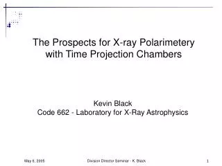
The Prospects for X-ray Polarimetery with Time Projection Chambers Kevin Black Code 662 - Laboratory for X-Ray Astrophysics Division Director Seminar - K. Black
Gas pixel detector polarimeter concept Track images Modulation Photoelectric polarimetery with a pixelized micropattern gas detector • Highly sensitive technique first demonstrated by Bellazzini et al (2001) • First practical device demonstrated by GSFC (2003) • Basis of the AXP SMEX proposal (awarded new technology funding) Division Director Seminar - K. Black
Limits of the pixelized detector technique • Electron diffusion in the drift region creates a tradeoff between quantum efficiency, modulation Polarimeter figure-of-merit vs energy Division Director Seminar - K. Black
X-ray Strip number Time of arrival Drift direction The time projection chamber (TPC) as a photoelectric polarimeter • Concept: create a virtual pixel detector from a strip detector by using time to derive the second coordinate • Construct pixels by digitizing the pulse-train waveform on each strip Division Director Seminar - K. Black
2. Geometry accommodates an imager below the TPC TPC polarimeter Pixel polarimeter Our proposed rocket instrument provides simultaneous observations with a time-projection and a pixel polarimeter Tradeoffs in a TPC polarimeter • ProsCons 1. Much greater quantum efficiency without loss of modulation • 1. Not imaging • 2. Fundamentally asymmetric: will require careful calibration and/or rotation • 3. Factor of 103 fewer electronics channels than a pixel polarimeter Division Director Seminar - K. Black
A demonstration TPC polarimeter • Constructed in 2 months from stuff we found along the side of the road • Thanks to Bob Baker, Ken Sims, Norman Dobson, Richard Koenecke • Components: • GEMs: off-the-shelf etched stainless steel foils (150 micron hex pitch) • Strip anode: standard printed circuit (150 micron pitch) • Commercial preamps • 24-channel digitizer based on 8-channel, 40 MHz ADC 24-channel waveform digitizer Stainless steel GEM The “roadkill” polarimeter Division Director Seminar - K. Black
Interaction point / Auger electron 6 keV photon in 0.3 atm CO2 End point / Bragg peak Digitized waveforms Derived image Demo TPC polarimeter operation • Goal: photoelectron track images using this TPC technique • Digitize raw charge-sensitive preamp signals at 25 MSPS • Drift velocity = 3.75 cm/microsecond (= 150 microns bins) Division Director Seminar - K. Black
Strip # (150 microns) Time Bin (40 nsec) A Sampling of Track Images 6 keV in 0.3 atm CO2 Division Director Seminar - K. Black
Next Steps • Quantitative demonstration of TPC as a polarimeter • Measure modulation with Roadkill II with: • 130 micron pitch micromegas using etched stainless steel foils • 24 channel, 50 MHz ADCs – operate near diffusion minimum • Polarized and unpolarized 6 keV • Rotation mechanism or drift velocity calibration Division Director Seminar - K. Black
Conclusion • Images of photoelectron tracks from a TPC are qualitatively comparable to those from a pixel detector. • A TPC-based photoelectric polarimeter is a promising complement to a pixel polarimeter or other focal plane instrument. • Further work is required to quantify these results and to understand and control systematic errors. Division Director Seminar - K. Black