Download
1 / 50
530 likes | 876 Views
This unit explores fractures and faults, their types, mechanics, and formation, aiding in understanding deformation sequences, construction risks, mineral exploration, and water flow in rocks. Study fracture orientations and associated joints and shears for valuable geological insights.

E N D
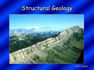
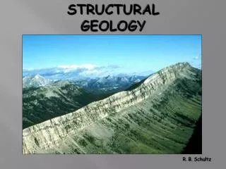
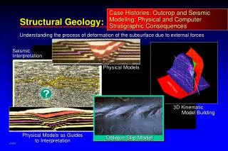
Structural Geology(Geol 305)Semester (071) Dr. Mustafa M. Hariri
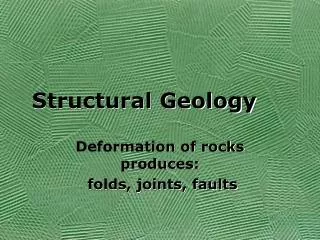
Objectives This unit of the course discusses Fractures and Faults By the end of this unit you will be able to: • Differentiate between the different type of fractures • Differentiate between the different type of faults • Understand the relationship between the different type of stresses and faults • Where faults form and how? • Faults mechanics • Role of fluid in faulting • Faults movement mechanisms • Shear, Shear zones and different type of shears
FRACTURE FRACTURE: is defined by Twiss and Moores (1992) as “..surfaces along which rocks or minerals have broken; they are therefore surfaces across which the material has lost cohesion” Characteristics of fractures according to Pollard and Aydin (1988) • fractures have two parallel surfaces that meet at the fracture front • these surfaces are approximately planar • the relative displacement of originally adjacent points across the fractures is small compared to the fracture length..
Fracture, Joint and Fault The term fracture encompasses both joints and faults. JOINTS: are fractures along which there has been no appreciable displacement parallel to the fracture and only slight movement normal to the fracture plane. Joints are most common of all structures present in all settings in all kind of rocks as well as consolidated and unconsolidated sediment
Types of Fractures Extensional FractureIn extensional fractures the Fracture plane is oriented parallel to σ1 and σ2 and perpendicular to σ3. Three types of fractures have been identified: • Mode I fractures (joints) it is the extensional fractures and formed by opening with no displacement parallel to the fracture surface (see above figure). • Mode II and Mode III are shear fractures. These are faults like fractures one of them is strike -slip and the other is dip-slip Same fracture can exhibit both mode II and mode III in different parts of the region.
Importance of studying joints and shear fractures • To understand the nature and sequence of deformation in an area. • To find out relationship between joints and faults and or folds. • Help to find out the brittle deformation in an area of construction (dams, bridges, and power plants. • In mineral exploration to find out the trend and type of fractures and joints that host mineralization which will help in exploration.
Importance of studying joints and shear fractures • Joints and fractures serve as the plumping system for ground water flow in many area and they are the only routes by which ground water can move through igneous and metamorphic rocks. • Joints and fractures porosity and permeability is very important for water supplies and hydrocarbon reservoirs. • Joints orientations in road cuts greatly affect both construction and maintenance. Those oriented parallel to or dip into a highway cut become hazardous during construction and later because they provide potential movement surfaces.
TYPES OF JOINT • Systematic joints: have a subparallel orientation and regular spacing. • Joint set: joints that share a similar orientation in same area. • Joint system: two or more joints sets in the same area • Nonsystematic joints:joints that do not share a common orientation and those highly curved and irregular fracture surfaces. They occur in most area but are not easily related to a recognizable stress. Some times both systematic and nonsystematic joints formed in the same area at the same time but nonsystematic joints usually terminate at systematic joints which indicates that nonsystematic joints formed later.
Type of Fractures • Plumose joints: joints that have feathered texture on their surfaces, and from this texture the direction of propagation of joints can be determined. • Veins: are filled joints and shear fractures and the filling range from quartz and feldspar (pegmatite and aplite) to quartz, calcite and dolomite.
Type of Fractures • Conjugate fractures: paired fracture systems, formed in the same time, and produced by tension or shear. Many of them intersect at an acute angle which will be bisected by the • Curved fractures: occur frequently and may be caused by the textural and compositional differences within a thick bed or large rock mass or they may a result of changes in stress direction or analysis. Cross cutting relationship and material filling the fractures can help in resolving the chronological order of deformation.
FRACTURE ANALYSIS Study of joints in an area will give information about the sequence and timing of formation. It will also provide information on the timing and geometry of the brittle deformation of the crust and the way fractures propagate through the rocks.
Importance of Fracture Orientation Study of orientation of systematic fractures provides information about the orientation of one or more principle stress directions involved in the brittle. Parameters measured for fractures are strike and dip. Or strike of linear features from aerial photos and landsat images. Data obtained from fractures is plotted in rose diagram or equal area net. Equal area net for strike and dip and rose diagram for strike only. Studies of joint and fracture orientation from LANDSAT and other satellite imagery and photographs have a variety of structural, geomorphic, and engineering applications.
Strain -ellipsoid analysis of joints in area may help to determine dominant crystal extension directions
Fold and Joints Joints may form during brittle folding in a position related to the fold axis and axial surface as follows • parallel • normal • oblique depending on stress condition.
Fault Related Joints • Joints are also formed adjacent to brittle faults, and movement along faults usually produces a series of systematic fractures. Most joints form by extensional fracturing of rock in the upper few kilometers of the Earth's crust. The limiting depth formation of extension fractures should be the ductile-brittle transition.
Factors Affecting the Formation of Joints • Rock type • Fluid pressure • Strain rate • Stress difference at a particular time
Characteristics of Fractures • Plumose structure: is the structures formed on the joint surface during its propagation and provides information about the joint propagation direction. • Hackle marks: indicate zones where the joint propagate rapidly. • Arrest line: forms perpendicular to the direction of propagation and is parallel to the advancing edge of fractures.
Characteristics of Fractures • Bedding and foliation planes in coarse-grained rocks constitute barriers to join propagation. Bedding in uniformly fine-grained rocks, such as shales and volcanicalstic rocks, appears to be less of barriers. • In sandstone bed propagation of joints through the bed is slightly offset from the layers above or below. • Variation in bed thickness also affects propagation direction. • In horizontal layering joints will not propagate from sandstone into shale if the least principle horizontal stress in shale is greater than that in sandstone. • Fractures will be terminated at the contact between the two rocks.
Joints Classified According to their Environment and Mechanism of Formations (Engelder, 1985) • Tectonic fracture • Hydraulic fracture • Unloading fracture • Loading fracture All of these types are based on the assumption that failure mechanism is tensile.
Tectonic fractures: Form at depth in response to abnormal fluid pressure and involve hydrofracturing. They form mainly by tectonic stress and the horizontal compaction of sediment at depth less than 3 km, where the escape of fluid is hindered by low permeability and abnormally high pore pressure is created. • Hydraulic fractures: Form as tectonic fractures by the pore pressure created due to the confined pressed fluid during burial and vertical compaction of sediment at depth greaterthan 5 km. Filled veins in low metamorphic rocks are one of the best of examples of hydraulic fractures.
Unloading fractures: Form near surface as erosion removes overburden and thermalelastic contraction occurs. They form when more than half of the original overburden has been removed. The present stress and tectonic activity may serve to orient these joints. Vertical unloading fractures occur during cooling and elastic contraction of rock mass and may occur at depths of 200 to 500 m. • Release fractures: Similar to unloading fractures but they form by release of stress. Orientation of release joints is controlled by the rock fabric. Released joints form late in the history of an area and are oriented perpendicular to the original tectonic compression that formed the dominant fabric in the rock. Release joints may also develop parallel to the fold axes when erosion begins and rock mass that was under burial depth and lithification begins to cool and contract, these joints start to propagate parallel to an existing tectonic fabric. Sheared fractures may be straight or curved but usually can't be traced for long distance.
Joints within Plutons Fractures form in pluton in response to cooling and later tectonic stress. Many of these joints are filled with hydrothermal minerals as late stage products. Different types of joints are present with pluton (i.e. longitudinal, and cross joints)
NONTECONIC FRACTURES • Sheeting joints: Those joints form subparallel to the surface topography. These joints may be more observed in igneous rocks. Pacing within these fractures increases downward. These fractures thought that they form by unloading overlong time when erosion removes large quantities of the overburden rocks. • Columnar joints and Mud Cracks: Columnar joints form in flows, dikes, sills and volcanic necks in response to cooling and shrinking of the magma.
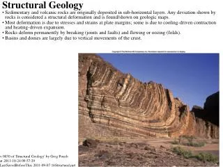
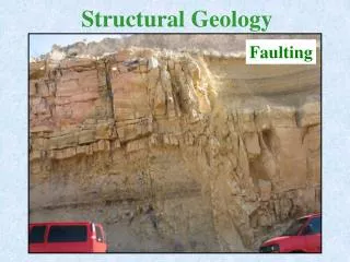
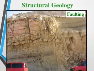
FAULT CLASSIFICATION AND TERMINALOGY Faults:Are fractures that have appreciable movement parallel to their plane. They produced usually be seismic activity. Understanding faults is useful in design for long-term stability of dams, bridges, buildings and power plants. The study of fault helps understand mountain building. Faults may be hundred of meters or a few centimeters in length. Their outcrop may have as knife-sharp edges or fault shear zone. Fault shear zones may consist of a serious of interleaving anastomosing brittle faults and crushed rock or of ductile shear zones composed of mylonitic rocks.
Parts of the Fault • Fault plane: Surface that the movement has taken place within the fault.On this surface the dip and strike of the fault is measured. • Hanging wall:The rock mass resting on the fault plane. • Footwall: The rock mass beneath the fault plane. • Slip:Describes the movement parallel to the fault plane. • Dip slip: Describes the up and down movement parallel to the dip direction of the fault. • Strike slip:Applies where movement is parallel to strike of the fault plane. • Oblique slip:Is a combination of strike slip and dip slip. • Net slip (true displacement): Is the total amount of motion measured parallel to the direction of motion
Separation: The amount op apparent offset of a faulted surface, measured in specified direction. There are strike separation, dip separation, and net separation. • Heave: The horizontal component of dip separation measured perpendicular to strike of the fault. • Throw: The vertical component measured in vertical plane containing the dip.
Features on the fault surface • Grooves (parallel to the movement direction) • Growth of fibrous minerals (parallel to the movement direction) • Slickensides are the polished fault surfaces. • Small steps. All are considered a kind of lineation. They indicate the movement relative trend NW, NE … etc. Small steps may also be used to determine the movement direction and direction of movement of the opposing wall. Slicklines usually record only the last moment event on the fault.
ANDERSON FAULTS CLASSIFICATION Anderson (1942) defined three types of faults: • Normal Faults • Thrust Faults • Wrench Faults (strike slip)
Normal Fault Normal Fault:The hanging wall has moved down relative to the footwall. Graben: consists of a block that has dropped down between two subparllel normal faults that dip towards each other. Horst : consists of two subparallel normal faults that dip away from each other so that the block between the two faults remains high. Listric: are normal faults that frequently exhibit (concave-up) geometry so that they exhibit steep dip near surface and flatten with depth. Normal faults usually found in areas where extensional regime is present.
Thrust Fault Thrust Fault Thrust Faults: In the thrust faults the hanging wall has moved up relative to the footwall (dip angle 30º or less) Reverse Faults: Are similar to the thrust faults regarding the sense of motion but the dip angle of the fault plane is 45º or more Thrust faults usually formed in areas of comperssional regime.
Strike-Slip Fault Strike-Slip Faults Strike-slip Faults: Are faults that have movement along strikes. There are two types of strike slip faults: A] Right lateral strike-slip fault (dextral): Where the side opposite the observer moves to the right. B] Left lateral strike-slip fault (sinistral): Where the side opposite the observer moves to the left. Note that the same sense of movement will also be observed from the other side of the fault.
Transform Faults Transform Faults:Are a type of strike-slip fault (defined by Wilson 1965). They form due to the differences in motion between lithospheric plates. They are basically occur where type of plate boundary is transformed into another. Main types of transform faults are: • Ridge-Ridge • Ridge-Arc • Arc-Arc
Other types of fault • en-echelon faults: Faults that are approximately parallel one another but occur in short unconnected segments, and sometimes overlapping. • Radial faults: faults that are converge toward one point • Concentric faults: faults that are concentric to a point. • Bedding faults (bedding plane faults): follow bedding or occur parallel to the orientation of bedding planes.
CRITERIA FOR FAULTING • Repetition or omission of stratigraphic units asymmetrical repetition • Displacement of recognizable marker such as fossils, color, composition, texture ..etc.). • Truncation of structures, beds or rock units. • Occurrence of fault rocks (mylonite or cataclastic or both) • Presence of S or C structures or both, rotated porphyry clasts and other evidence of shear zone. • Abundant veins, silicification or other mineralization along fracture may indicate faulting. • Drag Units appear to be pulled into a fault during movement (usually within the drag fold and the result is thrust fault) • Reverse drag occurs along listric normal faults. • Slickensides and slickenlines along a fault surface • Topographic characteristics such as drainges that are controlled by faults and fault scarps.
FAULTS MECHANICS Anderson 1942 defined three fundamental possibilities of stress regimes and stress orientation that produce the three types of faults (Normal, thrust, and strike-slip) note that σ1> σ2> σ3 • Thrust fault:σ1 and σ2 are horizontal and σ3 is vertical. Thus a state of horizontal compression is defined for thrust faults. Shear plane is oriented to σ1 with angle = or < 45º and // σ2. • Strike-Slip faults: σ1 and σ3 are horizontal and σ2 is vertical. Shear plane is oriented to σ1 with angle = or 45º and // σ3. Form also due to horizontal compression. • Normal faults: σ1 is vertical and σ2 and σ3 are horizontal. Shear plane is oriented 45º or less to σ1 and // σ2. Form due to horizontal extension or vertical compression.
Role of fluids in faulting Fluids plays an important role in faulting. They have a lubricating effect in the fault zone as buoyancy that reduces the shear stress necessary to permit the fault to slip. The effect of fluid on movement is represented as in landslide and snow avalanches.
Faults movement mechanisms Movement on faults occurs in two different ways: • Stick slip:(unstable frictional sliding) involves sudden movement on the fault after a long-term accumulation of stress. This stress probably the cause of earthquakes. • Stable sliding:involves uninterrupted motion along a fault, so stress is relieved continuously and does not accumulate. The two types of movement may be produced along the segments of the same fault. Stable sliding where ground water is abundant, whereas, stick-slip occur with less ground water
Other factor that control the type of movement is the curvature of the fault surface. • Withdrawal of ground water may cause near surface segments of active faults to switch mechanisms from stable sliding to stick slip, thereby increasing the earthquake hazard. • Pumping fluid into a fault zone has been proposed as a way to relieve accumulated elastic strain energy and reduce the likelihood of large earthquake, but the rate at which fluid should be pumped into fault zone remains unknown.
Fault Surfaces and Frictional sliding Fault surfaces between two large blocks are always not planar especially on the microscopic scale. This irregularities and imperfections are called asperities increase the resistance to frictional sliding. They also reduce the surface area actually in contact. The initial contact area may be as little as 10%, but as movement started the asperities will break and contact will be more.
Shear (frictional) Heating in Fault zones During movement of faults frictional heat is generated due to the mechanical work. The heat generated can be related to an increase in temperature. This friction heat is indicted by the formation of veins pseudotachylite (false glass) in many deep seated fault zones and the metamorphism along subduction zones (greenschist and blueschist facies). In some areas there is indication of temperature of 800ºc and 18 to 19 kb (60km depth). This indicate that they can form in the lower crust or upper mantle. Fault zones may also serve as conduit for rapid fluxing of large amounts of water and dissipation of heat during deformation. Generally friction-related heating along faults is a process that clearly occurs in the Earth, but difficult to demonstrate.
BRITTLE AND DUCTILE FAULTS Brittle faults occur in the upper 5 to 10 km of the Earth’s crust. In the upper crust consist of : Single movement Anastomosing complex of fracture surfaces. The individual fault may have knife-sharp contacts or it may consist of zone of cataclasite. At ductile-brittle zone 10-15km deep in continental crust, faults are characterized by mylonite. At surface of the crust mylonite may also occur locally where the combination of available water and increased heat permits the transition. The two types of fault may occur within one fault where close and at the surface brittle the associated rocks are cataclasts and at deep where ductile and brittle zone mylonite is present
SHEAR ZONE Shear zones are produced by both homogeneous and inhomogenous simple shear, or oblique motion and are thought of as zones of ductile shear. Shear zones are classified by Ramsay (1980) as: 1) brittle 2) brittle-ductile 3) ductile
Characteristics of Shear Zones Shear zones on all scales are zones of weakness. • Associate with the formation of mylonite. • Presence of sheath folds. • Shear zones may act both as closed and open geochemical systems with respect to fluids and elements. • Shear zones generally have parallel sides. • Displacement profiles along any cross section through shear zone should be identical.
INDICATORS OF SHEAR SENSE OF MOVEMENT • Rotated porphyroblasts and porphyroclasts. • Pressure shadows • Fractured grains. • Boudins • Presence of C- and S- surfaces (parallel alignment of platy mineral) • Riedel shears.