Download
1 / 38
380 likes | 633 Views
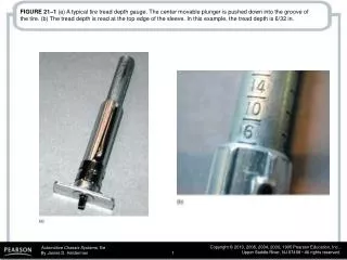
FIGURE 21–1 (a) A typical tire tread depth gauge. The center movable plunger is pushed down into the groove of the tire. (b) The tread depth is read at the top edge of the sleeve. In this example, the tread depth is 6/32 in.

E N D
FIGURE 21–1 (a) A typical tire tread depth gauge. The center movable plunger is pushed down into the groove of the tire. (b) The tread depth is read at the top edge of the sleeve. In this example, the tread depth is 6/32 in.
FIGURE 21–2 Wear indicators (wear bars) are strips of bald tread that show when the tread depth is down to 2/32 in., the legal limit in many states.
FIGURE 21–3 The tire tread runs around the circumference of the tire, and its pattern helps maintain traction. The ribs provide grip, while the grooves direct any water on the road away from the surface. The sipes help the tire grip the road.
FIGURE 21–4 Hydroplaning can occur at speeds as low as 30 mph (48 km/h). If the water is deep enough and the tire tread cannot evacuate water through its grooves fast enough, the tire can be lifted off the road surface by a layer of water. Hydroplaning occurs at lower speeds as the tire becomes worn.
FIGURE 21–5 Typical construction of a radial tire. Some tires have only one body ply, and some tires use more than two belt plies.
FIGURE 21–6 The major splice of a tire can often be seen and felt on the inside of the tire. The person who assembles (builds) the tire usually places a sticker near the major splice as a means of identification for quality control.
FIGURE 21–7 Tire construction is performed by assembling the many parts of a tire together on a tire-building machine.
FIGURE 21–8 After the entire tire has been assembled into a completed “green” tire, it is placed into a tiremolding machine where the tire is molded into shape and the rubber is changed chemically by the heat. This nonreversible chemical reaction is called vulcanization.
FIGURE 21–9 Notice that the overall outside diameter of the tire remains almost the same and at the same time the aspect ratio is decreased and the rim diameter is increased.
FIGURE 21–10 Cross-sectional view of a typical tire showing the terminology.
FIGURE 21–11 Typical sidewall markings for load index and speed rating following the tire size.
FIGURE 21–12 The E.C.E. symbol on a sidewall of a tire. Notice the small -s at the end, indicating that the tire meets the “pass-by” noise limits.
FIGURE 21–13 A typical door placard used on a General Motors vehicle indicating the recommended tire inflation. Note that the information also includes the tire size and speed rating of the tire as well as the recommended wheel size.
FIGURE 21–14 Conicity is a fault in the tire that can cause the vehicle to pull to one side due to the cone effect (shape) of the tire.
FIGURE 21–15 Notice the angle of the belt material in this worn tire. The angle of the belt fabric can cause a “ply steer” or slight pulling force toward one side of the vehicle.
FIGURE 21–16 Slip angle is the angle between the direction the tire tread is heading and the direction it is pointed.
FIGURE 21–17 Typical “Uniform Tire Quality Grading System” (UTQGS) ratings imprinted on the tire sidewall.
FIGURE 21–18 Typical DOT date code. This tire was built the sixth week of 2005.
FIGURE 21–19 Cutaway of a run-flat tire showing the reinforced sidewalls and the required pressure sensor.
FIGURE 21–20 A conventional tire on the left and a run-flat tire on the right, showing what happens when there is no air in the tire.
FIGURE 21–21 The PAX run-flat tire system is composed of three unique components—a special asymmetrical wheel, a urethane support ring, and special tire.
FIGURE 21–22 The Tire Performance Criteria (TPC) specification number is imprinted on the sidewall of all tires used on General Motors vehicles from the factory.
FIGURE 21–23 The size of the wheel is usually cast or stamped into the wheel. This wheel is 7 inches wide. The letter “J” refers to the contour of the bead seat area of the wheel.
FIGURE 21–24 The wheel rim well provides a space for the tire to fit during mounting; the bead seat provides a tire-to-wheel sealing surface; the flange holds the beads in place.
FIGURE 21–25 A cross section of a wheel showing part designations.
FIGURE 21–26 Offset is the distance between the centerline of the wheel and the wheel mounting surface.
FIGURE 21–27 Back spacing (rear spacing) is the distance from the mounting pad to the edge of the rim. Most custom wheels use this measurement method to indicate the location of the mounting pad in relation to the rim.
FIGURE 21–28 Bolt circle is the diameter of a circle that can be drawn through the center of each lug hole or stud. The bolt circle is sometimes referred to as PCD for pitch circle diameter.
FIGURE 21–29 Measuring the bolt circle on a five lug wheel is difficult, but a quick and easy way includes measuring as shown to determine the approximate bolt circle of a five-lug wheel.
FIGURE 21–30 Measure center-to-center distance and compare the distance to the figures in the chart in the text to determine the diameter for a five-lug bolt circle.
FIGURE 21–31 A typical JWL symbol for the Japan Wheel Light Metal standard mark.
FIGURE 21–32 (a) A rubber snap-in style tire valve assembly. (b) A metal clamp-type tire valve assembly used on most high-pressure (over 60 PSI) tire applications such as is found on many trucks, RVs, and trailers. The internal Schrader valve threads into the valve itself and can be replaced individually, but most experts recommend replacing the entire valve assembly every time the tires are replaced to help prevent air loss.